

- 25-35 Min Read
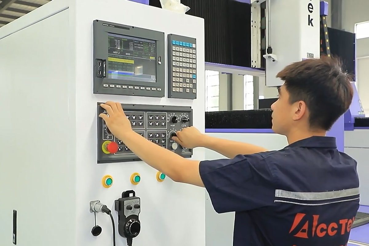
CNC routers have become essential tools in modern fabrication, widely used in industries ranging from woodworking and signage to plastics processing and light metal machining. At the heart of every successful CNC operation lies programming—the process of translating a design into machine-readable instructions that control movement, speed, and cutting actions. For beginners, however, CNC router programming often appears complex and technical. Concepts such as G-code, coordinate systems, toolpaths, and feed rates can seem overwhelming at first glance. These challenges can lead to hesitation, errors, or inefficient workflows if not addressed with the right guidance.
This article is designed to bridge that gap by providing a structured and practical introduction to CNC programming. Rather than focusing solely on theory, it breaks down key concepts into manageable sections, helping readers build a solid foundation step by step. Whether your goal is to operate a CNC router confidently, improve production efficiency, or expand your technical capabilities, this guide will provide the foundational knowledge you need. By the end of this article, you will have a clear understanding of how CNC router programming works and how to apply it effectively in real-world scenarios, setting the stage for continued growth in CNC machining.
Basics of CNC Router Programming
Understanding the basics of CNC router programming is the first step toward operating your machine with confidence and precision. At its core, CNC programming is the process of converting a digital design into a set of instructions that a CNC router can follow to perform cutting, engraving, or shaping operations. These instructions dictate every movement of the machine—where the tool goes, how fast it moves, how deep it cuts, and when auxiliary functions, such as the spindle, are activated. By learning these basics, beginners can build a clear mental model of how digital designs are transformed into physical machining operations, making it much easier to understand more advanced programming topics later in the process.
What is CNC Programming?
CNC programming refers to the creation of coded instructions—most commonly in the form of G-code—that control the behavior of a CNC router. These instructions tell the machine how to move along different axes (X, Y, and Z), what path to follow, and how to interact with the material.
In a typical workflow, a design is first created using CAD (Computer-Aided Design) software. This design is then processed in CAM (Computer-Aided Manufacturing) software, which converts the geometry into toolpaths and generates the corresponding G-code. Alternatively, simple programs can be written manually, especially for basic operations.
For beginners, it’s necessary to understand that CNC programming is not just about writing code—it’s about planning how a tool will interact with a material to achieve the desired result efficiently and safely.
How CNC Routers Interpret Code
To a CNC router, every job is simply a sequence of precise instructions. It does not interpret drawings or “understand” shapes—it follows commands. These commands are translated into motion and machine actions through three essential elements: the controller, the motion system with coordinates, and the machine axes. Understanding how these components work together will help beginners grasp how a CNC router turns code into real-world machining.
- Role of the Controller: The CNC controller serves as the “brain” of the router, responsible for reading the G-code program and converting it into actionable commands for the machine. It processes each line of code in sequence, interpreting instructions such as movement direction, speed, and machine functions, and then sends precise electrical signals to motors, drives, and the spindle. By coordinating all machine operations in real time, the controller ensures that every programmed action is executed accurately and in the correct order, making it a critical component in achieving consistent machining results.
- Motion Systems and Coordinates: The motion system is what physically carries out the instructions interpreted by the controller, using components such as stepper or servo motors, drive mechanisms, and feedback systems to move the cutting tool. These movements are guided by a coordinate system, where positions are defined numerically along specific directions. CNC routers typically operate using either absolute positioning, where all movements reference a fixed origin point, or incremental positioning, where each move is relative to the current position. This coordinate-based control enables precise, repeatable motion and ensures that the tool follows the intended path accurately.
- Overview of Machine Axes: CNC routers move along defined axes that represent directions in three-dimensional space, forming the foundation of all machining operations. The primary axes include the X-axis (left and right movement), Y-axis (forward and backward movement), and Z-axis (up and down movement), which together allow the machine to perform both 2D and 3D tasks. More advanced CNC routers may also incorporate additional rotary axes, such as A, B, or C axes, enabling complex machining on curved or multi-sided surfaces. Understanding how these axes function helps beginners visualize how programmed movements translate into real cutting actions.
Types of CNC Programming
CNC router programming can be approached in several different ways, depending on the user’s experience level, production requirements, and available tools. While the end goal is always the same, the method used to create the program can vary significantly in complexity and flexibility. Understanding the main types of CNC programming helps beginners choose the most suitable approach for their workflow, build confidence more quickly, and gradually develop the skills needed for more advanced machining tasks.
- Manual Programming: This involves writing G-code instructions line by line without relying on automated software. This method gives the programmer full control over every aspect of the machining process, including tool movement, feed rates, and spindle operations. It is especially useful for simple tasks, quick edits, or learning the fundamentals of CNC logic. However, it requires a solid understanding of G-code syntax and machine behavior, and it can become time-consuming and error-prone when dealing with complex geometries or multi-step operations.
- CAM Software Programming: CAM software programming is the most widely used approach, particularly for beginners and industrial applications. In this method, the user creates or imports a design from CAD software, then uses CAM tools to define machining strategies, select tools, and set cutting parameters. The software automatically generates the corresponding G-code based on these inputs. This greatly simplifies the programming process, reduces the likelihood of errors, and allows users to handle complex shapes and toolpaths efficiently, making it the preferred choice for most CNC router operations.
- Conversational Programming: Conversational programming is a user-friendly method available on some CNC controllers, where the operator inputs machining parameters through guided menus or prompts directly on the machine interface. Instead of writing G-code manually, the user selects operations and enters values like dimensions, depths, and speeds. The controller then generates the necessary code automatically. While this approach is easy to learn and ideal for simple or repetitive tasks, it is typically limited in flexibility and may not support more advanced or highly customized machining requirements.
The basics of CNC router programming provide the essential groundwork for everything that follows in CNC operation and programming. Once you understand how programs are structured, how machines interpret instructions, and how different programming methods work, you gain the ability to approach CNC machining with greater confidence and clarity. These foundational concepts not only help reduce errors but also prepare you to learn more advanced techniques, optimize toolpaths, and improve overall machining efficiency.
Understanding G-Code and M-Code
G-code and M-code are the essential building blocks of CNC router programming, forming the language that communicates every instruction to the machine. While G-code primarily defines tool movements such as positioning, cutting paths, and travel motions, M-code controls auxiliary machine functions like spindle activation, tool changes, and program execution. Together, these codes allow a CNC router to translate a digital design into precise, coordinated physical actions. Understanding how they work is a crucial step for beginners, as it provides the foundation for reading, writing, and troubleshooting CNC programs effectively.
What is G-Code?
G-code is the fundamental programming language used to control CNC machines. It is a standardized set of instructions that tells the machine how to move, where to move, and what actions to perform during machining operations. Each line of G-code represents a specific command, such as moving the tool to a position, cutting along a path, or adjusting speed and feed rates.
At its core, G-code translates digital design information into precise machine movements. For example, it can instruct the router to move rapidly to a starting point, cut a straight line at a controlled feed rate, or follow a circular path. It also works alongside other commands to control machine behavior, such as turning the spindle on or off.
Although G-code may look complex at first, it follows a logical structure that becomes easier to understand with practice. Most modern CAM software automatically generates G-code, but learning its basics is still important for troubleshooting, editing programs, and gaining full control over CNC machining processes.
Common G-Codes for Beginners
For beginners learning CNC router programming, understanding a small set of commonly used G-codes is far more important than memorizing the entire language. These essential commands control the most basic and frequently used machine movements, forming the foundation of nearly every CNC program.
- G00 – Rapid Positioning: G00 is used to move the cutting tool quickly between points without cutting material. It is typically used for non-cutting movements such as traveling from the home position to the start of a job or moving between operations. Since speed is prioritized over precision during G00 moves, the tool is raised safely above the workpiece to avoid collisions.
- G01 – Linear Interpolation: G01 is one of the most important commands in CNC programming. It moves the tool in a straight line while actively cutting material at a controlled feed rate. This command is used for most cutting operations, including profiling edges, cutting slots, and engraving straight paths. The feed rate parameter determines how fast the tool moves through the material.
- G02 – Circular Interpolation (Clockwise Arc): G02 instructs the machine to move the tool along a clockwise arc. It is commonly used for curved cuts, rounded corners, and circular features. The arc is defined by parameters such as radius or center point coordinates, allowing precise control over curved toolpaths.
- G03 – Circular Interpolation (Counterclockwise Arc): G03 performs the same function as G02 but in a counterclockwise direction. Together, G02 and G03 allow CNC routers to create smooth curves and complex rounded geometries that are difficult to achieve with straight-line movements alone.
- G90 – Absolute Positioning Mode: G90 sets the machine to interpret all coordinates relative to a fixed origin point (work zero). This is the most commonly used positioning mode because it provides consistency and reduces the risk of cumulative positioning errors during machining.
- G91 – Incremental Positioning Mode: G91 switches the machine into incremental mode, where each movement is based on the current tool position rather than a fixed origin. This mode is useful for repetitive movements or relative adjustments but requires careful use to avoid positioning mistakes.
Common M-Codes
M-codes are used in CNC programming to control the auxiliary (non-motion) functions of a CNC router. While G-codes handle tool movement and cutting paths, M-codes manage machine actions such as spindle control, coolant systems, and program execution. For beginners, learning a few core M-codes is enough to understand how the machine is started, operated, and safely stopped during a job.
- M03 – Spindle ON (Clockwise Rotation): M03 turns the spindle on in a clockwise direction, which is the standard rotation for most CNC cutting tools. It is usually paired with an “S” value that defines spindle speed (RPM), such as S12000 for 12,000 RPM. This command is essential for all cutting operations.
- M04 – Spindle ON (Counterclockwise Rotation): M04 activates the spindle in a counterclockwise direction. It is less commonly used in standard CNC router work but may be required for specific tools or machining processes where reverse rotation improves cutting performance or tool behavior.
- M05 – Spindle Stop: M05 stops the spindle rotation completely. It is typically used at the end of a machining operation or before tool changes to ensure safe handling of the machine.
- M06 – Tool Change: M06 is used to initiate a tool change. On machines with automatic tool changers (ATC), this command triggers the system to switch to a different tool according to the program. On manual machines, it prompts the operator to change the tool before continuing.
- M08 – Coolant ON: M08 turns on the coolant system, which helps reduce heat, remove chips, and improve cutting performance. While more common in metal machining, some CNC routers also use dust or mist systems controlled by this command.
- M09 – Coolant OFF: M09 turns off the coolant or auxiliary cooling system. It is usually placed after a cutting operation or before program completion.
M30 – Program End and Reset: M30 signals the end of a CNC program. It stops all machine functions, resets the program to the beginning, and prepares the machine for the next run.
A clear understanding of G-code and M-code is fundamental to mastering CNC router programming. These command sets work together to control both the motion and operational behavior of the machine, ensuring that every step of the machining process is executed accurately and safely. Once beginners become familiar with the most commonly used codes, they gain the ability to interpret CNC programs with confidence, make simple modifications when needed, and develop a stronger overall grasp of how CNC machines function in real-world applications.
Coordinate Systems and Work Offsets
Coordinate systems and work offsets are the foundation of accurate CNC router operation, defining how digital instructions are translated into precise physical movements on the machine. Every CNC program relies on a clearly established reference system to determine where cutting begins, how toolpaths are positioned, and how multiple machining tasks are managed on the same setup. For beginners, understanding these concepts is essential because even correctly written code will produce incorrect results if the coordinate system is not properly defined or applied.
Machine Coordinate System vs Work Coordinate System
The machine coordinate system and work coordinate system are two fundamental reference systems in CNC router operation, and understanding the difference between them helps with accurate programming and setup.
- The machine coordinate system (MCS) is the machine’s fixed, built-in reference framework. It is defined by the manufacturer and represents the absolute limits and reference positions of the CNC router. Typically, the machine establishes its home position through a homing process at startup, which sets the zero point for all axes. This system does not change during normal operation and is used internally by the controller to track the machine’s physical position within its working range.
- The work coordinate system (WCS) is user-defined and specific to each job or workpiece. It allows the operator to set a custom origin point—commonly referred to as “work zero”—on the material being machined. Systems such as G54, G55, and others are used to store these offsets. The work coordinate system enables the same machine to perform different jobs without altering the machine’s global reference, simply by redefining the starting point for each task.
Setting Work Zero (Origin)
Setting the work zero, also known as the origin point, is one of the most important setup steps in CNC router programming. It defines the exact starting reference position for all machining movements on a specific workpiece. Since CNC programs rely entirely on coordinate-based instructions, an incorrectly set origin can lead to misaligned cuts, wasted material, or even machine collisions. For beginners, understanding how to properly establish work zero is essential for ensuring accuracy and consistency in every job.
- Setting X and Y Zero: To set the X and Y origin, the operator physically moves the cutting tool (or uses the machine’s jog controls) to the desired starting position on the material. Once positioned, the controller is instructed to set that point as X0 and Y0 for the active work coordinate system (such as G54). This defines the horizontal reference for all subsequent tool movements.
- Setting Z Zero: Z zero determines the vertical reference point and is especially important for cutting depth accuracy. Typically, the tool is lowered until it just touches the surface of the material, and this position is set as Z0. Some workflows may instead reference the machine bed, but setting Z zero at the material surface is more common in CNC routing because it ensures consistent cutting depth. A touch plate, tool setter, or manual paper method can be used to improve accuracy during this step.
Common Work Offsets (G54–G59)
In CNC router programming, work offsets such as G54 to G59 are used to define multiple independent coordinate systems within a single machine. These offsets allow operators to assign different origin points for different workpieces, setups, or machining stages without changing the machine’s global reference system. For beginners, understanding work offsets can provide flexibility in production, improve efficiency in multi-part machining, and reduce the need for repeated manual zero setting.
- G54–G59 Overview and Usage: G54 to G59 are standard work coordinate systems built into most CNC controllers. Each one acts as a separate “virtual origin”that stores a unique X, Y, and Z reference point. Once a work offset is set, all movements in the program are calculated relative to that specific origin. Each offset can store its own X, Y, and Z zero values, allowing operators to switch between them simply by calling the appropriate G-code in the program.
- Practical Application in CNC Routing: Work offsets are especially useful in production environments where multiple parts are machined on the same table. Instead of resetting the machine origin for every part, the operator can assign each part a different offset (e.g., G54 for part A, G55 for part B). The CNC program can then switch between these offsets automatically, improving workflow efficiency and reducing setup time. This is also helpful when using multiple fixtures or when machining different areas of a large sheet.
Coordinate systems and work offsets are fundamental to ensuring accuracy in CNC machining. They allow operators to define a precise reference point for each job, enabling the machine to execute programmed movements in the correct physical location every time. By mastering how to set and manage work zeros and offsets, beginners can significantly reduce setup errors, improve machining consistency, and build a stronger foundation for more advanced CNC programming techniques.
Tooling and Toolpath Fundamentals
Tooling and toolpath fundamentals represent one of the most important aspects of CNC router programming, as they directly determine how effectively a design is translated into a physical product. While G-code defines machine behavior, it is the choice of cutting tools and the design of toolpaths that ultimately influence machining quality, efficiency, and surface finish. For beginners, understanding how tools interact with different materials and how toolpaths guide cutting motion is essential for achieving accurate, safe, and professional CNC results.
Types of CNC Router Bits
CNC router bits are the cutting tools that physically shape the material, and their design directly determines the quality, accuracy, and efficiency of machining results. Different bit geometries are engineered for specific tasks such as cutting, engraving, carving, or finishing. For beginners, choosing the right tool affects surface finish, cutting speed, and tool life.
- End Mills (Flat End Bits): These are the most commonly used CNC router bits and are designed for general-purpose cutting. End mills have a flat cutting end that allows for precise profiling, slotting, and pocketing operations.
- V-Bits (Engraving Bits): V-bits are shaped like a “V” and are primarily used for engraving, lettering, and decorative carving. The angle of the bit determines the width and depth of the cut, making it ideal for detailed work.
- Ball Nose Bits: Feature a rounded cutting tip and are commonly used for 3D contouring and surface finishing. They are ideal for machining smooth curves, molds, and complex three-dimensional shapes.
- Compression Bits: Designed to reduce tear-out on both the top and bottom surfaces of laminated materials such as plywood or MDF. They combine up-cut and down-cut flute designs, pushing chips toward the center of the material.
- Straight Flute Bits: Straight flute bits are commonly used for plastics and soft materials. Their straight cutting edges help reduce heat buildup and prevent material melting or deformation.
Tool Selection for Different Materials
Selecting the right CNC router tool for a specific material is a critical factor in achieving clean cuts, efficient machining, and long tool life. Different materials respond differently to cutting forces, heat, and chip evacuation, meaning that a tool that performs well on wood may fail on aluminum or plastics. For beginners, understanding how material properties influence tool choice helps avoid common issues such as burning, melting, tear-out, or premature tool wear.
- Wood: The most commonly machined material on CNC routers and is generally forgiving. Up-cut end mills are effective for removing chips and preventing clogging, while down-cut end mills produce a cleaner top surface by pressing fibers downward. For laminated materials like plywood or MDF, compression bits are often preferred because they reduce tear-out on both the top and bottom edges.
- Plastics: Require careful tool selection because they are sensitive to heat buildup, which can cause melting or poor edge quality. Single-flute or polished end mills are commonly used because they provide better chip clearance and reduce friction. Sharp cutting edges and proper chip evacuation are essential to prevent material fusion.
- Aluminum and Non-Ferrous Metals: Requires rigid, sharp, and properly coated cutting tools due to its strength and tendency to stick to cutting edges. Carbide end mills with 2 or 3 flutes are commonly used to balance chip removal and cutting stability. Lubrication or air blast systems are often applied to reduce heat and prevent chip welding.
- Foam and Soft Materials: Foam, EVA, and similar soft materials require minimal cutting force and high chip evacuation efficiency. Single-flute or large-helix end mills are often used to prevent material tearing and ensure smooth cutting.
Toolpath Strategies
Toolpath strategies define how a CNC router moves the cutting tool through material to achieve a desired shape or surface. Even with the correct G-code and proper tooling, poor toolpath planning can result in inefficient machining, rough surface finishes, or excessive tool wear. Basic toolpath strategies directly impact machining quality, processing time, and overall production efficiency.
- Profile Cutting: Also known as contouring, is used to cut along the outer or inner boundary of a shape. It is one of the most common CNC operations and is widely used for producing parts, panels, and signage. Depending on the setup, the tool can cut on the line, inside the line, or outside the line, which determines the final dimensions of the workpiece.
- Pocketing Toolpaths: Pocketing involves removing material from within a defined boundary to create recessed areas or cavities. This strategy is commonly used for engraving, engraving backgrounds, and creating functional recesses such as slots or housings. Pocketing toolpaths are typically generated using multiple passes to gradually remove material, which improves tool life and reduces cutting load on the machine.
- Drilling Toolpaths: They are used to create precise holes at specific locations. The CNC router moves the tool directly to a coordinate point and plunges vertically into the material. This method ensures consistent hole placement and depth control. Peck drilling strategies may also be used for deeper holes to improve chip evacuation and reduce tool stress.
- Roughing vs. Finishing Strategies: Roughing toolpaths are designed for rapid material removal, prioritizing speed over surface quality. These paths often leave a small amount of material behind for a final finishing pass. Finishing toolpaths, then remove this remaining material with lighter cuts and slower feed rates to achieve smooth surfaces and precise dimensions. Combining both strategies improves efficiency while maintaining high-quality results.
- 3D Contouring Toolpaths: 3D contouring is used for machining complex surfaces such as molds, sculptures, and organic shapes. The tool follows continuous paths across varying depths to reproduce detailed three-dimensional geometry. Ball nose cutters are commonly used for this strategy to achieve smooth surface transitions and fine detail reproduction.
Tooling and toolpath fundamentals form the bridge between CNC programming and real-world machining results. By understanding different router bits, selecting appropriate tools for specific materials, and applying effective toolpath strategies, beginners can significantly improve machining accuracy and surface quality. Mastering these basics not only reduces errors and tool damage but also lays the groundwork for more advanced and efficient CNC operations.
Introduction to CAM Software
As CNC machining has evolved, CAM software has become an essential tool for simplifying and streamlining the programming process. Instead of manually writing complex G-code, users can rely on CAM systems to generate accurate toolpaths and machine instructions through a guided, visual workflow. For beginners, this significantly reduces the learning curve and minimizes the risk of programming errors, making CNC technology more accessible and efficient to use.
What is CAM Software?
CAM (Computer-Aided Manufacturing) software is a specialized tool used to convert digital designs into machine-readable instructions for CNC equipment. It acts as the bridge between CAD (Computer-Aided Design) models and the actual machining process, transforming geometric designs into precise toolpaths and generating the corresponding G-code that controls a CNC router.
In a typical workflow, a user first creates or imports a design in CAD software. The CAM software then allows the user to define machining parameters such as tool selection, cutting depth, feed rate, and spindle speed. Based on these inputs, the software automatically calculates the most efficient paths for the cutting tool and generates a complete CNC program that the machine can execute.
One of the key advantages of CAM software is its ability to simplify complex programming tasks. Instead of manually writing G-code, users can rely on visual interfaces and automated features to generate accurate and optimized machining instructions. This is especially valuable for beginners, as it reduces the risk of errors and makes it easier to handle intricate shapes and multi-step operations.
Basic CAM Workflow
A structured CAM workflow helps transform a digital design into a precise and executable CNC machining process. For beginners, following a clear sequence of steps reduces errors, improves efficiency, and ensures consistent results. While different CAM software may vary slightly in interface, the core workflow remains largely the same across most platforms.
- Import or Create a CAD Design: The process begins with a digital model, typically created in CAD software or imported from an external file. This design defines the geometry that will be machined and serves as the foundation for all subsequent steps.
- Define Material and Setup: Next, the user specifies the workpiece size and position within the CAM environment. This includes setting the material dimensions, thickness, and orientation, as well as defining the work coordinate system.
- Select Tools and Cutting Parameters: In this step, the appropriate cutting tools are chosen based on the material and machining requirements. The user also defines key parameters such as feed rate, spindle speed, depth of cut, and step-over.
- Generate Toolpaths: The CAM software uses the design and selected parameters to generate toolpaths. Different strategies are applied depending on the geometry and desired outcome.
- Simulate and Verify: Before sending the program to the machine, the toolpaths are simulated within the CAM software. This step allows users to visually check for errors such as collisions, incorrect depths, or missed areas.
- Post-Process to Generate G-Code: Once the toolpaths are verified, the CAM software converts them into G-code using a post-processor tailored to the specific CNC machine. This ensures compatibility between the program and the machine controller.
- Transfer and Execute the Program: Finally, the generated G-code is transferred to the CNC router via USB, network, or direct connection. The operator sets up the machine, verifies the work zero, and runs the program to begin machining.
Benefits for Beginners
For those new to CNC machining, CAM software offers a practical and accessible way to begin programming without needing deep knowledge of G-code. It simplifies complex processes through visual interfaces and automation, which makes the learning curve smoother and more manageable.
- Reduced Learning Complexity: CAM software eliminates the need to manually write G-code, enabling beginners to generate machining programs through guided steps and intuitive menus. This lowers the barrier to entry and helps users get started quickly.
- Minimized Programming Errors: Automated toolpath generation and built-in safeguards reduce the risk of common mistakes such as incorrect coordinates or unsafe movements. This leads to more reliable and predictable machining results.
- Visual Toolpath Simulation: Most CAM systems provide simulation features that allow users to preview the machining process before running it on the machine. This helps beginners identify issues like collisions, missed areas, or incorrect depths in advance.
- Easier Handling of Complex Designs: CAM software can efficiently process intricate geometries and multi-step operations that would be difficult to program manually. This enables beginners to take on more advanced projects earlier in their learning journey.
- Improved Efficiency and Productivity: By automating many aspects of programming, CAM software significantly reduces setup time and increases overall workflow efficiency. Beginners can complete projects faster and with greater consistency.
Understanding the role of CAM software is a key step in mastering CNC router programming. By automating toolpath generation and providing simulation and verification tools, CAM systems allow beginners to produce accurate and efficient machining results with greater confidence. As users gain experience, CAM software continues to support more advanced capabilities, making it an indispensable part of modern CNC workflows.
Step-by-Step Beginner Programming Workflow
For beginners, CNC router programming becomes much easier when approached through a clear, structured workflow. Instead of approaching CNC programming as a complex and fragmented process, breaking it into sequential stages helps beginners understand how each step connects to the next. From creating a design to generating toolpaths and running the final G-code on the machine, this workflow ensures that users can learn systematically while reducing the risk of errors and improving overall machining confidence.
Create or Import a Design
Every CNC machining project begins with a digital design that defines the shape, size, and features of the final product. For beginners, ensuring that the design is accurate and properly prepared helps avoid issues later in the workflow.
- Creating a Design from Scratch: Designs are typically created using CAD software, where users draw 2D profiles or build 3D models. For simple CNC router projects, such as signs or panels, 2D vector drawings are often sufficient. More complex parts, such as molds or 3D carvings, require detailed 3D modeling.
- Importing Existing Designs: Instead of creating a design from scratch, users can import files from external sources. Common file formats include DXF / SVG for 2D vector designs, as well as STL / STEP / IGES for 3D models. When importing a design, it is important to check for scaling issues, missing geometry, or incompatible elements.
Define Material and Setup
Next, you specify the size, thickness, and position of the workpiece (stock) in the CAM software. A proper setup ensures that toolpaths align accurately with the physical material.
- Stock Size and Positioning: In CAM software, the user specifies the length, width, and thickness of the material, ensuring it matches the actual workpiece placed on the machine. The position of the stock relative to the work coordinate system must also be defined accurately.
- Clamping and Fixturing: Common methods include mechanical clamps, vacuum tables, double-sided tape, or custom jigs and fixtures. When setting up clamps, it is important to position them outside the toolpath area to avoid collisions with the cutting tool.
Select Tools and Cutting Parameters
These choices directly affect cutting quality, machining efficiency, tool life, and overall safety. For beginners, understanding how to match tools with materials and set proper cutting conditions helps achieve consistent and reliable results.
- Tool Selection Basics: Choosing the correct tool depends on the material, type of operation, and desired finish. Key considerations include tool type, tool diameter, flute count, and tool material. Proper tool selection ensures efficient cutting, reduces wear, and improves surface quality.
- Feed Rate: It refers to how fast the cutting tool moves through the material during machining. If the feed rate is too high, it may cause tool breakage or rough cuts; if too low, it can lead to burning, melting, or excessive tool wear. Finding the correct balance is essential for optimal performance.
- Spindle Speed: It determines how fast the cutting tool rotates. Different materials require different spindle speeds—for example, wood generally allows higher speeds, while metals require more controlled settings. Spindle speed must be properly matched with feed rate to maintain an effective cutting process.
- Depth of Cut|: It refers to how much material is removed in a single pass along the Z-axis. Taking deeper cuts increases efficiency but also raises cutting forces and tool stress. Beginners are advised to use conservative step-down values to ensure stable and safe machining.
Generate Toolpaths
Generating toolpaths is the stage in CAM software where a digital design is converted into actual machining instructions for the CNC router. At this point, the software calculates how the cutting tool will move through the material to create the desired shape.
- Selecting the Machining Strategy: Before generating toolpaths, the user must choose an appropriate machining strategy based on the design and operation type. Common strategies include profiling for cutting outlines, pocketing for removing internal material, and drilling for creating precise holes.
- Toolpath Calculation Process: It determines the exact X, Y, and Z movements required for the tool to follow the design geometry. This includes generating entry and exit points, cutting passes, and retract movements to ensure safe and efficient machining.
- Visual Preview of Toolpaths: Before finalizing, the generated toolpaths are displayed visually within the software. This preview allows users to inspect how the tool will move across the material.
Post-Process to G-Code
Post-processing is the final step in CAM programming, where the designed toolpaths are converted into machine-readable G-code. While toolpaths describe how the tool should move in a general sense, different CNC machines require specific code formats and command structures.
- Selecting the Correct Machine Format: Each CNC router model or control system may require a different output format. Beginners should always verify that the selected post-processor matches their CNC machine specification.
- G-Code Generation Process: Once the post-processor is selected, the CAM software converts the toolpaths into a sequence of G-code commands. This includes instructions for movement, machine functions, coordinates, feed rates, and spindle speeds. The result is a complete program file that the CNC router can read and execute line by line.
- Code Review and Verification: After generating the G-code, review the output before sending it to the machine. Many CAM systems allow users to inspect the raw code or run a simulation to verify accuracy. Checking for issues such as incorrect tool changes, missing commands, or unsafe movements helps prevent machining errors and potential damage.
- File Formats and Transfer Methods: The final G-code file is typically saved in formats such as .nc, .tap, or .gcode, depending on the machine requirements. This file can then be transferred to the CNC router via USB drive, network connection, or direct software integration.
Following a structured programming workflow helps beginners approach CNC machining with clarity and confidence. By progressing step by step—from design creation and setup to toolpath generation, simulation, and execution—beginners can better understand each stage of the process and how they influence the final result. This approach not only improves accuracy and efficiency but also helps develop consistent habits. As experience grows, this workflow becomes second nature, forming the foundation for more advanced CNC programming and production processes.
Simulation and Dry Run
Simulation and dry run are essential verification steps in CNC programming that provide an opportunity to identify potential issues before executing the actual machining process. These methods allow users to preview tool movements, detect errors, and ensure that the program runs safely and efficiently. For beginners, using simulation and dry run helps build confidence and minimizes the risk of machine damage, material waste, and inaccurate cuts. By thoroughly checking the program in a controlled environment, users can ensure that the CNC machine operates as intended.
Types of Simulation
Simulation in CNC programming is a crucial verification step that allows users to preview machining operations before they are executed on the actual machine. It helps identify errors, visualize tool movement, and ensure safe and efficient machining.
- Software Simulation: Software simulation is performed within CAM or CNC control software before sending the program to the machine. It visually reproduces the tool’s movements, showing how it will cut through the material step by step. This allows users to check for issues such as incorrect cutting paths, missing operations, or potential tool collisions. It is a fast and safe way to validate the program and make adjustments before any physical machining takes place.
- Dry Run on the Machine: A dry run is performed directly on the CNC router without cutting actual material. In this mode, the machine follows the programmed toolpath, often with the spindle turned off or the tool raised above the workpiece. This helps verify real machine movement, axis limits, and overall program behavior. It is especially useful for detecting clearance issues, fixture interference, or unexpected rapid movements.
What to Check Before Cutting
Before beginning a CNC machining job, ensure that the program is free from errors and that the machine setup is correct. This final check involves verifying the toolpath, identifying potential collision risks, and ensuring that the machine’s travel limits are respected. For beginners, this process can prevent costly mistakes, protect tools and machinery, and achieve accurate results.
- Toolpath Accuracy: Accurate toolpaths are the foundation of any CNC operation. Verify that the toolpaths are in the correct sequence, starting with roughing operations and progressing to finishing passes. Ensure the cutting depth for each pass is correct, especially for deep cuts or materials with varying hardness. In addition, check that the toolpaths include safe retract movements, ensuring the tool clears the material and any clamps during rapid movements.
- Collision Risks: Ensure the tool does not interfere with clamps, fixtures, or other machine components. Double-check that the tool does not pass through the material in areas where it should not, potentially damaging both the tool and the workpiece. Use CAM software to simulate the toolpath and check for any visible collisions in the virtual environment. This can help identify areas where the tool may encounter obstacles during machining.
- Travel Limits: Ensure the toolpath stays within the movement range of each machine axis (X, Y, Z). Verify that the length of the tool used in the program is correctly accounted for. If the tool is too long or incorrectly positioned, it might try to reach an area that is physically unreachable within the machine’s range. Additionally, ensure that the workpiece is positioned in a way that respects the machine’s travel limits.
Simulation and dry run are critical steps for verifying the accuracy and safety of CNC programs before cutting begins. By utilizing both software simulation and a physical dry run on the machine, beginners can catch potential issues such as incorrect toolpaths, collisions, and setup errors. These checks not only help prevent costly mistakes but also contribute to safer and more efficient CNC machining operations. Developing the habit of always verifying a program helps beginners build confidence, improve accuracy, and ensure reliable CNC machining results.
Tips for Improving CNC Programming Skills
CNC programming is a skill that improves over time with consistent practice, problem-solving, and learning from experience. For beginners, mastering the basics and progressively working on more complex tasks is key to becoming a proficient CNC programmer. Whether you’re working with CNC routers, mills, or lathes, several strategies can help sharpen your skills. These tips will guide you through practical ways to enhance your understanding, boost your confidence, and ultimately improve your CNC programming ability.
Practice with Simple Designs First
Starting with simple projects is a great way to learn the fundamental principles of CNC programming without feeling overwhelmed. Begin with basic shapes like circles, squares, or rectangles, and work your way up to more complex geometries as you gain experience. Simple designs allow you to focus on mastering the key aspects of programming—such as tool selection, feed rates, and basic toolpath generation—before moving on to advanced techniques.
- Tip: Try machining parts like nameplates, basic signage, or simple 2D shapes. This will help you understand the flow of creating G-code and running a CNC machine without the complexity of intricate designs.
Learn to Read and Edit G-code Manually
While most CNC programs are generated by CAM software, learning to read and edit G-code manually provides a deeper understanding of how the CNC machine operates. Understanding G-code syntax and being able to troubleshoot or modify code can be incredibly valuable, especially when custom modifications or fixes are needed.
- Tip: Start by examining the G-code generated by your CAM software, identifying commands for movement (G0, G1), spindle speed (S), tool changes (M6), and feed rates (F). Then, try manually adjusting values such as feed rates or tool paths for more advanced learning.
Keep a Parameter Reference Notebook
A parameter reference notebook is an invaluable tool for tracking common settings, machine limitations, and material-specific information. As you learn, note the parameters that work best for specific materials and the machine settings that give you the best results.
- Recommended spindle speeds and feed rates for common materials.
- Tool dimensions and settings for frequently used tools.
- Common G-code commands and their functions.
- Notes on past mistakes and how they were resolved.
Analyze Mistakes and Optimize Toolpaths
Mistakes are inevitable in CNC programming, but they are also growth opportunities. When things go wrong, take the time to analyze what happened and figure out what went wrong—was it an incorrect toolpath, an error in G-code, or a setup issue? Learning from these mistakes helps prevent them from happening again in the future.
- Tip: After completing a job, review any issues that arose during machining (e.g., rough edges, tool wear, or machine crashes). Adjust your toolpaths, cutting parameters, or machine setup to optimize future operations.
Engage with CNC Communities and Forums
The CNC world is filled with experienced machinists and programmers who are often willing to share their knowledge and advice. Engaging with online communities and forums can expose you to a wealth of information and troubleshooting tips that can help you improve. You can ask for feedback, share your experiences, and learn from others who have faced similar challenges.
- Tip: Join CNC-related forums, Facebook groups, or online communities like Reddit’s r/CNC or Practical Machinist. Participate in discussions, ask questions, and contribute your experiences. You’ll gain insights that you may not encounter in formal tutorials or manuals.
Improving your CNC programming skills takes time, practice, and a willingness to learn from both successes and setbacks. By starting with simple designs, gaining a solid understanding of G-code, keeping a parameter reference notebook, learning from mistakes, and engaging with the CNC community, you’ll gradually build up your expertise. As you continue to refine these skills, you’ll become more confident and efficient in your CNC programming, leading to higher-quality results and a deeper understanding of the machining process.
Summarize
CNC router programming may seem complex at first, but by following a structured, beginner-focused approach, it becomes much more accessible and rewarding to learn. Understanding key fundamentals such as coordinate systems, G-code, tooling, and CAM workflows allows beginners to gradually progress from simple tasks to more advanced machining. Equally important is developing good habits like verifying setups, running simulations, and optimizing toolpaths to improve accuracy, safety, and efficiency. With consistent practice and a willingness to learn from experience, beginners can steadily build confidence and evolve into skilled CNC programmers capable of handling increasingly complex projects. If you already possess extensive experience in operating CNC routers, the article “What Skills Should an Advanced CNC Router Operator Learn?” will be of greater value to you.
AccTek CNC stands out as a reliable and professional manufacturer of CNC routers, offering a wide range of machine models designed to meet diverse user needs—from hobbyists to industrial-scale production. With a strong focus on customization, the company ensures that each solution is tailored to specific materials, applications, and performance requirements. In addition to high-quality equipment, AccTek CNC provides comprehensive after-sales technical support, helping users quickly resolve issues and optimize machine performance. This combination of flexible product offerings and dependable service makes AccTek CNC a trusted partner for businesses seeking efficient, precise, and scalable CNC machining solutions.