

- 15-20 Min Read
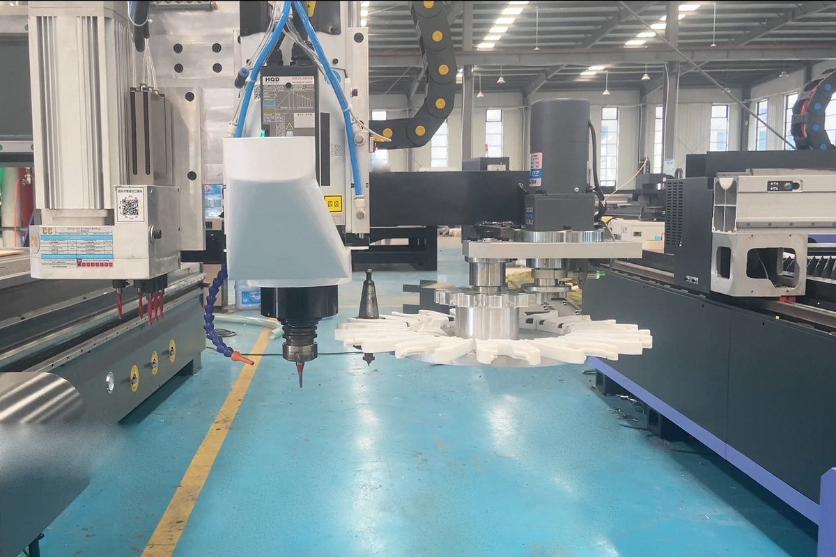
In modern CNC routing, efficiency, precision, and automation are no longer optional—they are essential. Central to achieving these goals is the Automatic Tool Changer (ATC) system, a mechanism that seamlessly swaps cutting tools without manual intervention. From the tool magazine where tools are stored to the spindle where cutting occurs, every component of the ATC system works in perfect harmony to make automated tool changes seamless. But how exactly does an ATC system operate? How does a tool travel from the storage magazine to the spindle with perfect alignment every time?
This article takes a detailed look at the full mechanism of CNC router ATC systems. We will explore the key components, including tool holders, actuators, sensors, and control software, and explain the step-by-step tool change process. You’ll also learn about different ATC designs, safety features, maintenance practices, and troubleshooting tips—all beneficial for maximizing machine performance. By understanding how tools move “from magazine to spindle,” operators and technicians can ensure reliable operation, reduce errors, and fully leverage the advantages of automated CNC routing.
What Is an Automatic Tool Changer (ATC)?
An Automatic Tool Changer (ATC) is one of the most impactful innovations in modern CNC routers, enabling machines to perform complex, multi-step operations without constant operator intervention. By examining its definition, core functions, and how it compares to traditional manual tool changing, we can gain a clearer picture of why ATC systems have become a standard requirement in modern machining environments.
Definition and Core Functions
An Automatic Tool Changer (ATC) is a precision-engineered system built into CNC routers to automatically swap cutting tools without manual intervention. Instead of stopping the machine, the ATC performs the entire sequence through a coordinated series of mechanical actions. This automated process not only reduces downtime but also enables the CNC router to complete multi-step machining operations efficiently and accurately. At a basic level, an ATC serves three core functions:
- Store multiple tools in an organized magazine or rack.
- Select and retrieve the correct tool based on programmed instructions.
- Securely clamp the new tool in the spindle and verify that it is ready for machining.
These functions allow CNC routers to shift seamlessly between tasks such as rough cutting, profiling, drilling, slotting, pocketing, and finishing without the need for operator involvement.
ATC in Comparison to Manual Tool Changing
While manual changes rely heavily on operator involvement and vary based on skill and technique, ATC systems automate the entire process using precise mechanical and electronic control. This contrast highlights why ATCs are becoming increasingly essential in modern CNC routing environments. Here are the key differences between manual and automatic tool changing:
- Speed: Manual tool changes can take several minutes, especially for inexperienced operators. ATC tool changes are completed in seconds, dramatically reducing cycle time.
- Precision: Manual tool insertion depth, collet tightening, and offsets can vary between operators, leading to inconsistency. ATC tool clamping force and positioning are controlled by the machine, ensuring repeatable accuracy.
- Workflow Efficiency: Manual requires constant operator involvement and frequent machine stops. ATC enables continuous machining, even for jobs needing multiple tools.
- Error Reduction: Manual higher risk of incorrect tool installation, misalignment, or offset mistakes. ATC sensors confirm correct tool engagement, reducing human error.
- Productivity Impact: The manual is suitable for simple tasks or low-frequency tool changes. ATC is ideal for complex, multi-step jobs and high-volume production environments.
With its ability to store tools, select them automatically, and clamp them with precision, an Automatic Tool Changer offers significant advantages over manual tool changing in both speed and consistency. The comparison highlights just how much time and variability manual changes introduce and underscores the value of automation in maintaining productivity and accuracy. Understanding these foundational concepts sets the stage for exploring the individual components of an ATC system and how they work together to move tools efficiently from magazine to spindle.
Key Components of a CNC Router ATC System
A CNC router’s Automatic Tool Changer operates through a coordinated network of mechanical, pneumatic, and electronic components. Each part plays a specific role in ensuring that tools are stored securely, selected accurately, and transferred smoothly to and from the spindle. Understanding these components helps operators troubleshoot issues, maintain performance, and appreciate the engineering behind automatic tool changing.
Tool Magazine / Tool Rack
The tool magazine is the storage hub for all cutting tools used in the machining process. It organizes tools in fixed pockets or slots, ensuring each has a designated location for quick retrieval. Common types include:
- Linear tool racks: Simple, affordable, and mounted along the machine bed or gantry.
- Carousel or Disc-Type Magazines: Faster tool access with a rotating structure.
- Chain-style Magazines: High-capacity systems for largeindustrial CNC routers.
A durable and dust-protected magazine ensures reliable tool storage and prevents contamination that could affect clamping accuracy.
Tool Holders and Collets
Tool holders connect the cutting tool to the spindle and ensure accurate alignment and rotational balance. CNC routers equipped with ATC systems most often use standardized tool holder interfaces to ensure compatibility and precision. The most common types include:
- ISO (e.g., ISO30): Widely used in woodworking routers; durable and versatile.
- BT (e.g., BT30, BT40): Balanced and symmetrical for high-speed machining.
- HSK (e.g., HSK63): Offers excellent accuracy and rigidity, especially for high RPM applications.
- ER Collets: They are the most widely used collet type due to their flexibility and precision. ER collets come in various sizes to match different tool shank diameters.
Proper tool holders reduce vibration, maintain cutting accuracy, and support high-speed machining.
Pneumatic or Electric Actuators
ATC systems rely on actuators to clamp and release tools. Most CNC routers use pneumatic systems, which deliver consistent pressure to operate the spindle’s drawbar mechanism. Functions include:
- Activating the clamp/unclamp sequence
- Controlling tool release
- Operating air cylinders in the magazine or changer arm
Stable air pressure is required, as fluctuations can lead to failed tool changes or unsafe clamping conditions.
Spindle with Automatic Clamping Mechanism
The spindle is equipped with an internal drawbar that grips the tool holder using spring-loaded force or pneumatic pressure. During a tool change, the system momentarily releases tension to allow the tool to be inserted or removed. Key features include:
- High-precision bearings
- Tool presence sensors
- Anti-drop safety mechanisms
- Air blast ports to remove dust before clamping
This ensures secure tool seating and reduces the risk of tool slippage during high-speed cutting.
Tool Length Measurement System
To maintain precise cutting depth and avoid collisions, the CNC router must measure each tool’s length after installation. Two main types of tool measurement systems are used:
- Contact Tool Setters: The tool touches a calibrated sensor block to register length.
- Laser Tool Measurement Systems: A beam detects exact tool tips for higher precision.
Automatic offset detection allows the machine to adjust cutting paths without manual calibration.
Control System and Software
The CNC controller is the “brain” coordinating the entire ATC mechanism. It manages:
- Tool numbers and assignments in the tool table
- Tool change commands (usually via M6 macros)
- Movement sequences to and from the magazine
- Safety checks and sensor feedback
- Error detection and recovery instructions
Well-programmed control logic prevents collisions, ensures smooth transitions, and synchronizes tool changes with machining operations.
Each component of a CNC router’s ATC system works together to make automatic tool changing fast, accurate, and reliable. By understanding how these parts function and interact, operators can maintain their machines effectively, troubleshoot issues efficiently, and fully leverage the advantages of automation over manual tool changes. This foundation prepares us to explore the step-by-step tool change process, showing how tools move seamlessly from magazine to spindle in a fully automated sequence.
The Full Tool Change Sequence: How the System Works
Understanding the step-by-step operation of a CNC router’s Automatic Tool Changer (ATC) helps illustrate how precision, speed, and reliability are achieved during automated machining. The sequence involves several coordinated movements, controlled by the machine’s software and executed by mechanical components such as the spindle, tool magazine, actuators, and sensors. Below is a breakdown of the process from magazine to spindle.
Pre-Tool Change Preparation
Before any tool movement occurs, the CNC controller ensures the machine is in a safe state:
- The spindle stops rotating and, if necessary, cools down.
- The machine moves to a designated tool change position, often a safe height above the workpiece.
- Sensors verify that no obstruction exists between the spindle and magazine.
- The controller activates the tool change command (commonly M6).
This preparation prevents collisions and ensures a smooth, controlled tool change.
Tool Release Process
The currently installed tool is released from the spindle:
- Pneumatic or electric actuators release the drawbar, allowing the tool holder to disengage.
- Sensors confirm the tool has been fully unclamped.
- The tool is carefully lowered or moved to an intermediate position before being transferred to the magazine.
This stage requires ensuring precision to prevent tool damage and maintain alignment.
Moving to the Tool Magazine
Once released, the tool or spindle moves to the magazine:
- For linear magazines, the spindle moves along the gantry to the correct slot.
- For carousel or disc-type magazines, the rotating mechanism positions the required pocket beneath the spindle.
- Sensors verify that the tool pocket is correctly aligned and ready to receive the tool.
This step ensures that both the old and new tools are accurately positioned for safe handling.
Tool Placement in the Magazine
The removed tool is placed into its assigned magazine slot:
- Positioning is carefully controlled to prevent misalignment or jamming.
- Some systems use a brief air blast to clean the tool pocket or tool holder before storage.
- Sensors confirm that the tool is securely seated in its slot.
Proper placement maintains the magazine’s organization and ensures that tools are ready for the next operation.
Picking Up the New Tool
The ATC retrieves the next tool from the magazine:
- The spindle or changer arm moves to the designated slot containing the new tool.
- The tool is engaged by the spindle’s drawbar and clamped using pneumatic or electric actuators.
- Sensors confirm proper tool engagement and secure clamping.
At this stage, precision is necessary to avoid runout, ensure correct tool length, and maintain machining quality.
Post-Tool Change Verification
After the new tool is installed, the system performs several checks before resuming machining:
- Tool length measurement updates the CNC offsets automatically.
- Sensors verify that the tool is seated properly and ready for cutting.
- Optional runout or vibration checks may be performed.
- Once all confirmations are positive, the machine resumes the programmed toolpath.
This final step ensures the new tool is fully ready for operation, maintaining both accuracy and safety.
The full tool change sequence demonstrates how an ATC CNC router transforms a potentially slow, manual process into a rapid, automated operation. By understanding this sequence, operators and technicians can better appreciate the engineering behind ATC systems and ensure their machines operate at peak performance during multi-tool production tasks.
Sensors, Safety Features, and Diagnostics
While the mechanical components of an ATC CNC router handle the physical movement of tools, the system’s sensors, safety features, and diagnostics ensure that each tool change is executed accurately and reliably. These elements monitor tool presence, prevent collisions, detect errors, and provide critical feedback to the CNC controller. By integrating safety and diagnostic systems with mechanical operations, ATCs maintain high precision, reduce downtime, and protect both the machine and operator during automated tool changes.
Tool Presence and Clamping Sensors
Sensors play a critical role in verifying that each tool is correctly engaged and secured:
- Optical or mechanical sensors detect whether the tool is fully seated in the spindle.
- The system can confirm successful clamping and prevent machining from starting if the tool is misaligned or missing.
- These sensors also help the ATC detect empty magazine slots or incorrect tool placement.
By providing real-time feedback, tool sensors ensure that each tool change is executed safely and reliably.
Collision Prevention Systems
ATC systems incorporate safeguards to prevent collisions between moving parts:
- Proximity sensors monitor the positions of the spindle, tool changer, and magazine.
- Limit switches and software soft limits stop the machine if components move beyond safe boundaries.
- Coordinated control logic ensures that tools and machine axes never interfere with each other during a change.
Collision prevention protects both the machine and cutting tools from damage, reducing downtime and repair costs.
Dust Prevention and Blowing Systems
Dust and debris can compromise both clamping accuracy and sensor performance. Many ATC systems include:
- Air blast nozzles that clean tool pockets and tool shanks before engagement.
- Protective covers or shrouds around the magazine to reduce dust accumulation.
Maintaining a clean environment improves tool life, spindle reliability, and sensor accuracy.
Emergency Stop and Error Handling
Even with advanced automation, unexpected errors can occur. ATC systems include:
- Emergency stop functions that immediately halt the machine if a problem arises.
- Controller alarms and diagnostics to indicate issues such as unclamped tools, misaligned pockets, or sensor failures.
- Some machines provide automatic recovery procedures, allowing safe resumption of operations after minor errors.
These safety features and diagnostic tools help operators address problems quickly while minimizing the risk of accidents or machine damage.
Sensors, safety mechanisms, and diagnostic systems are the backbone of reliable ATC operation. They ensure that tools are correctly clamped, movements are safe, and potential issues are detected before they cause damage. Together with the mechanical components, these systems allow CNC routers to perform fast, accurate, and safe tool changes, enabling continuous machining with minimal risk and maximum efficiency.
Integration With CAM Software and Machine Control
An automatic tool changer is most effective when it works seamlessly with a CNC router’s CAM software and machine controller. This integration ensures that tool changes occur precisely when needed, with the correct tool and settings, and in full synchronization with the machining program. By linking the mechanical actions of the ATC with the intelligence of the software, operators can execute complex, multi-tool operations efficiently, reduce downtime, and maintain consistent machining accuracy.
Tool Table Setup and Identification
CAM software and the CNC controller rely on a tool table that contains information about each cutting tool, including:
- Tool number and ID
- Tool type (e.g., end mill, drill, engraving bit)
- Tool diameter, length, and offsets
- Recommended spindle speeds and feed rates
When the CNC program calls for a tool change, the ATC uses this table to identify the correct tool in the magazine and retrieve it accurately. Maintaining an updated and accurate tool table helps reliable ATC CNC router operation.
Tool Change Commands
Automatic tool changes are triggered through standard G-code commands, most commonly the M6 command. The process works as follows:
- The CAM program inserts the M6 command at the appropriate point in the toolpath.
- The CNC controller interprets the command and initiates the ATC sequence.
- The spindle pauses, moves to a safe position, releases the current tool, and retrieves the new one.
- Sensors confirm tool engagement before machining resumes.
Some advanced CNC controllers allow custom ATC macros for specialized tool handling, further enhancing flexibility and efficiency.
Synchronization with Toolpaths
Seamless integration ensures that tool changes are coordinated with the machining program:
- The controller moves the spindle to a safe position above the workpiece before a change.
- Tool offsets are automatically applied after measurement or verification.
- The CAM-generated toolpath resumes precisely where it left off, preventing errors or collisions.
Proper synchronization reduces downtime and allows the machine to execute complex, multi-tool operations without manual intervention.
Error Prevention and Diagnostics
Integration also allows software-level monitoring and error handling:
- The controller checks for tool presence, magazine alignment, and spindle readiness.
- Alarms or automatic pauses occur if a tool is missing or clamping fails.
- Advanced systems can log tool usage, track wear, and alert operators when maintenance is required.
This combination of hardware and software intelligence makes ATC systems safer, more reliable, and more productive.
The integration of ATC systems with CAM software and machine control transforms tool changing from a mechanical task into a fully automated, intelligent process. Coordinated tool identification, change commands, and toolpath synchronization ensure that multi-tool operations are executed smoothly, accurately, and safely. This level of integration not only improves productivity but also enhances the reliability and precision of CNC routing, making automated machining a practical and powerful solution for modern manufacturing.
Maintenance Requirements for ATC Systems
An Automatic Tool Changer (ATC) is a vital part of a CNC router’s efficiency and accuracy, but like all mechanical systems, it requires regular maintenance to function optimally. Neglecting maintenance can lead to tool misalignment, clamping failure, or even spindle damage, resulting in costly downtime and reduced machining quality. Maintenance for ATC systems can be categorized into daily, weekly/monthly, and long-term tasks.
Daily Maintenance
Regular, simple tasks ensure that the system remains clean, lubricated, and calibrated, allowing for efficient tool changes and minimizing downtime during production. Here are the key components of daily ATC maintenance:
- Cleaning tool holders and pockets: Remove dust, chips, and debris from the magazine and spindle to prevent clamping errors.
- Checking pneumatic lines and air pressure: Ensure the actuators operate smoothly and with consistent force.
- Visual inspection: Look for obvious signs of wear, loose bolts, or misaligned components.
- Lubrication check: Some systems require light lubrication on moving parts to reduce friction.
Performing these tasks daily helps maintain smooth tool changes and prevents minor issues from escalating.
Weekly / Monthly Maintenance
While daily maintenance focuses on keeping the ATC system clean and functional, weekly and monthly maintenance ensure that key components are lubricated, calibrated, and thoroughly checked for wear. Below are the essential tasks to perform on a weekly or monthly basis:
- Lubricating sliding or rotating components: Bearings, linear guides, and actuator slides need proper lubrication for consistent movement.
- Inspecting drawbars, collets, and clamps: Check for wear, deformation, or damage that could affect clamping precision.
- Sensor inspection: Ensure optical or mechanical sensors are clean and functioning properly.
- Magazine inspection: Verify that tool pockets are not worn or misaligned and that tools fit securely.
This maintenance level helps prevent mechanical failures and keeps the ATC system operating at peak performance.
Long-Term Maintenance
Long-term maintenance focuses on preventive tasks, component replacement, and calibration to keep the ATC performing at peak efficiency and accuracy for years. This level of maintenance involves deeper inspection and calibration:
- Replacing worn components: Springs, pneumatic seals, actuator parts, or worn tool holders should be replaced before failure occurs.
- Calibrating the tool measurement system: Ensure accurate tool length detection and proper offset settings.
- Controller and firmware updates: Keep the CNC controller and ATC software up to date for improved functionality and safety.
- Full system diagnostics: Periodically perform a full check of ATC operation, including tool retrieval, clamping, and sensor feedback.
These tasks prolong the life of the ATC system and maintain reliable, high-precision operation over years of use.
Proper maintenance of a CNC router’s ATC system is necessary for reliability, accuracy, and safety. Daily cleaning and inspection, weekly lubrication and sensor checks, and long-term component replacement and calibration ensure that the ATC continues to perform smoothly. A well-maintained system not only reduces downtime and repair costs but also guarantees consistent tool changes, protecting both tools and the spindle while maximizing productivity.
Common Problems and Troubleshooting Tips for ATC Systems
While Automatic Tool Changer (ATC) systems are designed for reliability and precision, like any complex machinery, they can experience occasional issues. Understanding common problems and how to troubleshoot them helps minimize downtime and ensure smooth tool changes. This section highlights some of the most frequent ATC issues and offers practical solutions for resolving them.
Tool Not Changing Properly
The most common issue with ATC systems is the failure to execute a tool change properly. The tool may not be retrieved from the magazine, or the tool may not engage in the spindle. Here are the troubleshooting tips:
- Check magazine alignment: Ensure that the tool magazine is aligned with the spindle and that the tool pockets are properly positioned.
- Inspect actuators and air pressure: Verify that pneumatic actuators have sufficient air pressure and that there are no air leaks in the system.
- Clean and inspect sensors: Ensure that tool presence and clamping sensors are clean and functioning properly. Test sensors by manually engaging the tool and verifying the feedback.
- Clear magazine jams: Check for debris or tool misplacement inside the magazine. Clear any jams and ensure the magazine rotates freely.
- Inspect the drawbar and clamping mechanism: If the tool isn’t securely engaged, check the spindle’s drawbar for damage or wear. Replace any worn parts to restore proper clamping.
Tool Not Clamped Properly
The tool may not be properly clamped in the spindle, which can lead to tool slippage during machining. Here are the troubleshooting tips:
- Check clamping mechanism: Inspect the drawbar and clamping surface for wear or damage. Replace any worn parts to ensure a tight and secure fit.
- Verify air pressure: Ensure the pneumatic system supplies adequate air pressure for clamping, typically between 6 and 8 bar. Inspect air filters and regulators for blockages or damage.
- Align spindle and tool holder: Verify that the tool holder fits properly into the spindle. Misalignment may prevent proper clamping and could be caused by worn or damaged tool holders.
Tool Not Detected by Sensors
The ATC system fails to detect the tool, causing an error or preventing the tool change process from completing. Here are the troubleshooting tips:
- Clean sensors: Dust and debris can interfere with sensor functionality. Use a soft brush or compressed air to clean optical sensors and ensure they are free of obstructions.
- Check sensor connections: Inspect wiring and connections to ensure that sensors are properly connected to the machine’s controller. If wiring appears damaged, replace it.
- Verify tool placement: Ensure that tools are placed correctly in the magazine and spindle, and that sensors are aligned to detect the tool’s position.
Pneumatic or Electric Actuator Malfunctions
Pneumatic or electric actuators may fail to properly engage or move the tool changer’s components, resulting in incomplete tool changes or system malfunctions. Here are the troubleshooting tips:
- Inspect pneumatic components: Check for air leaks in hoses, fittings, or valves. Replace any damaged pneumatic components and verify that the air pressure is within the recommended range.
- Lubricate electric actuators: For electric actuators, ensure that the moving components are adequately lubricated. If misalignment is noticed, recalibrate or adjust the actuator positioning.
- Test actuator movement: Manually initiate actuator movements via the CNC controller to ensure proper function. If the actuator moves slowly or erratically, check for mechanical resistance or electrical issues.
Tool Magazine Not Rotating or Moving
The tool magazine may fail to rotate, move, or position tools correctly, preventing tool retrieval or storage. Here are the troubleshooting tips:
- Clear obstructions: Check for debris or misaligned tools in the magazine. Clean the tool pockets and ensure there is no interference preventing the magazine from rotating or moving.
- Inspect the rotary motor or actuator: Test the motor or actuator driving the magazine for proper operation. If the motor appears faulty, inspect the electrical connections and replace the motor if needed.
- Lubricate moving components: Check the magazine’s mechanical components, such as gears or rails, for signs of wear. Lubricate the moving parts to ensure smooth operation.
Troubleshooting ATC system issues requires a methodical approach, beginning with simple checks and progressing to more in-depth inspections as needed. By addressing common problems such as tool clamping failures, actuator malfunctions, and sensor issues, operators can maintain smooth and accurate tool changes. Regular inspections and prompt action can minimize downtime, prevent further damage, and ensure that the ATC continues to function reliably.
Summarize
The Automatic Tool Changer system is a cornerstone of modern CNC router operations, transforming what would otherwise be a time-consuming manual process into a streamlined, efficient, and automated sequence. From the magazine to the spindle, the ATC system incorporates a complex interplay of components—each designed to ensure accurate, reliable, and safe tool changes. By understanding the full mechanism behind the ATC, operators can ensure consistent performance, reduce downtime, and maximize productivity. Continue reading “What Top Features Should You Look for in an ATC CNC Router?” for a systematic approach to choosing a machine.
AccTek CNC is a leading manufacturer of high-quality CNC routers, offering a wide range of machines to meet the diverse needs of industries from sign-making to woodworking, metalworking, and beyond. Whether you’re looking for a 3-axis, 4-axis, 5-axis, or rotary axis CNC router, AccTek provides cutting-edge technology to enhance productivity, accuracy, and efficiency. Our expert team offers not only exceptional machine performance but also comprehensive technical support, ensuring that customers can maximize the potential of their CNC equipment. Choose AccTek CNC for a solution that drives your business forward with state-of-the-art technology and unparalleled service.