

- อ่าน 35-45 นาที
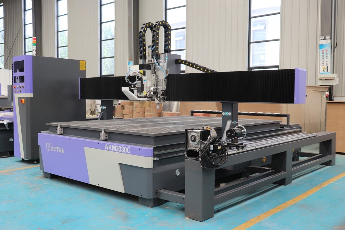
A เราเตอร์ CNC แกนหมุน expands the capabilities of traditional CNC machining by allowing the machine to process cylindrical, curved, and complex three-dimensional workpieces with greater flexibility and precision. By adding a rotary axis, CNC routers can perform operations such as engraving around cylinders, carving columns, machining furniture components, and producing intricate decorative parts that are difficult to achieve with standard 3-axis systems. However, achieving accurate rotary machining results requires more than simply installing the rotary attachment. Proper setup, software configuration, and calibration are key to ensure smooth rotation, precise positioning, and consistent machining quality.
Small errors in alignment, center height, or rotary axis parameters can lead to inaccurate dimensions, uneven surfaces, or machining defects. This guide provides a step-by-step overview of setting up and calibrating a rotary-axis CNC router, covering everything from installation and electrical connections to software settings, axis calibration, and common troubleshooting methods. Whether you are adding a rotary axis to an existing CNC router or optimizing an integrated rotary CNC system, following the proper setup procedures will help maximize machine performance, improve accuracy, and extend your equipment’s service life.
Understanding the Rotary Axis of a CNC Router
A rotary axis is an advanced CNC router attachment or integrated component that enables the machine to rotate a workpiece while the cutting tool moves along multiple axes. Unlike a standard เราเตอร์ CNC 3 แกน, which typically moves along the X, Y, and Z axes, a rotary axis introduces an additional rotational movement, usually called the A-axis. This allows the CNC router to machine around the entire surface of cylindrical or irregularly shaped materials, creating complex 3D designs, smooth contours, and detailed engravings with improved efficiency.
เครื่องเราเตอร์ CNC แบบแกนหมุนคืออะไร?
A rotary axis CNC router is a CNC machining system equipped with a rotary device that holds and rotates the workpiece during processing. The rotary axis works together with the machine’s linear axes to control both the position and rotation angle of the material, enabling operations such as turning, engraving, carving, and cutting on multiple sides without manually repositioning the workpiece. In a typical setup, one end of the workpiece is secured by a chuck, while the other end is supported by a tailstock. The rotary motor then drives the workpiece to rotate at precise angles according to the programmed tool path. The CNC controller coordinates the rotary movement with the X, Y, and Z movements of the cutting tool, allowing the machine to create continuous patterns and complex geometries. Compared with conventional CNC routers, rotary axis CNC routers provide several advantages:
- Machining of Complex Shapes: A rotary axis enables the CNC router to process cylindrical, curved, and irregularly shaped workpieces that are difficult or impossible to machine with a standard 3-axis system. It allows users to create detailed carvings, spiral patterns, rounded edges, and complex contours with greater design flexibility.
- Reduced Workpiece Repositioning: A rotary axis allows the material to rotate automatically during machining, reducing setup time, minimizing alignment errors, and improving overall production efficiency.
- Higher Machining Accuracy and Consistency: Since the workpiece remains fixed in the rotary fixture throughout the machining process, the risk of positioning errors caused by repeated clamping is significantly reduced. This helps achieve more precise dimensions and consistent results.
- Greater design flexibility: Expands CNC applications beyond flat panel processing. This versatility allows businesses to take on more diverse projects.
Main Types of Rotary Axis Configurations
Rotary axis systems for CNC routers are available in several configurations, each designed to meet different machining requirements, production volumes, and application needs. The right configuration depends on factors such as workpiece size, machining complexity, frequency of rotary operations, and desired level of automation.
- 4th-Axis Rotary Attachment: A 4th-axis rotary attachment is the most common option for CNC routers. It is installed on the machine bed and connected to the CNC controller as an additional axis. This type is ideal for users who need occasional rotary machining capabilities while maintaining the flexibility of a standard CNC router.
- Integrated Rotary Axis CNC Router: Some CNC routers are designed with a built-in rotary axis system. These machines usually provide better rigidity, easier setup, and improved alignment because the rotary unit is optimized for the machine structure. They are suitable for manufacturers who frequently process cylindrical or 3D workpieces.
- Dual Rotary Axis System: Advanced CNC systems may use multiple rotary axes to provide additional machining flexibility. These configurations are commonly used for complex industrial applications requiring simultaneous multi-axis movement and highly detailed 3D machining.
Key Components of a Rotary Axis System
A rotary axis system consists of several mechanical and electronic components that work together to rotate the workpiece accurately while coordinating with the CNC router’s linear movements. Each component has a specific function that contributes to machining precision, stability, and efficiency.
- Rotary Chuck: The primary clamping component that securely holds one end of the workpiece and transfers rotational motion from the drive system. It ensures that the material remains stable during machining and helps maintain accurate positioning, reducing vibration and improving surface quality.
- Tailstock: Supports the opposite end of the workpiece, especially when machining long or heavy materials. By keeping the workpiece aligned with the rotary axis centerline, it improves stability, minimizes deflection, and helps achieve more precise machining results.
- Rotary Drive Motor: Provides the power needed to rotate the workpiece according to CNC commands. Stepper motors are commonly used for standard applications, while servo motors are preferred for high-precision machining that requires higher speed, torque, and positioning accuracy.
- Gearbox or Reduction System: Connects the motor to the rotary shaft and adjusts the relationship between speed and torque. It increases rotational force, improves positioning accuracy, and allows the rotary axis to handle heavier workpieces and more demanding machining operations.
- Rotary Shaft and Coupling: The rotary shaft transfers the motor’s rotational force to the chuck, while the coupling connects the motor and shaft while compensating for minor alignment errors. These components must maintain high rigidity and precision to ensure smooth rotation and prevent machining inaccuracies.
- Mounting Brackets and Fixtures: Secure the rotary axis unit to the CNC router bed and maintain proper alignment with the machine’s coordinate system. A stable mounting structure helps prevent movement, vibration, and alignment issues during machining operations.
- Rotary Axis Controller and Driver: Manage communication between the CNC system and the rotary axis motor. They convert programmed commands into precise rotational movements while controlling factors such as rotation direction, speed, acceleration, and positioning accuracy.
Common Applications of Rotary Axis CNC Routers
Rotary-axis CNC routers significantly expand the capabilities of traditional CNC machining by enabling the processing of cylindrical, curved, and three-dimensional workpieces. With the ability to rotate materials during cutting, engraving, and carving operations, these machines are widely used in industries that require complex shapes, detailed patterns, and multi-sided machining.
- Woodworking and Furniture Manufacturing: Rotary axis CNC routers are widely used in woodworking applications for producing cylindrical and decorative components, such as stair balusters, table legs, chair parts, columns, and wooden crafts. The rotary axis allows manufacturers to create intricate carvings, spiral designs, and symmetrical patterns on round workpieces with high precision and repeatability.
- Musical Instrument Production: In the musical instrument industry, rotary axis CNC routers are commonly used to manufacture components with curved or cylindrical surfaces, including guitar necks, drum shells, and other instrument parts. The rotary function enables smooth shaping and detailed engraving while maintaining consistent dimensions and surface quality.
- Sign Making and 3D Engraving: Rotary axis systems are ideal for creating decorative signs, cylindrical nameplates, logos, and engraved patterns on round objects. Unlike flat-bed CNC routers, rotary axis machines can engrave continuously around the entire surface of a workpiece, making them suitable for customized products and artistic designs.
- Artistic Sculptures and Custom Crafts: Artists and craftsmen use rotary axis CNC routers to create complex sculptures, statues, and customized decorative items. The ability to machine around multiple sides of a workpiece allows for greater creative freedom and enables the production of detailed three-dimensional artwork with consistent quality.
The rotary axis is a valuable enhancement that transforms a standard CNC router into a more versatile machining solution. From 4th-axis attachments to integrated systems, different rotary configurations provide options for various production needs, while components such as the chuck, tailstock, motor, and controller work together to ensure precise rotation and stable machining. With its ability to handle complex shapes and multi-sided processing, a rotary axis CNC router opens up new possibilities in woodworking, engraving, and other industries, making it an important tool for manufacturers seeking greater flexibility and productivity.
Preparation Before Setting Up the Rotary Axis
Proper preparation is a critical first step before setting up a rotary axis on a CNC router. A well-prepared installation process not only helps ensure smooth integration between the rotary system and the CNC machine but also reduces the risk of alignment errors, compatibility issues, and operational failures. Before installation, users should verify machine compatibility, prepare the necessary tools, and inspect rotary axis components. Completing these preparation steps provides a solid foundation for accurate calibration, reliable operation, and optimal machining performance.
Check CNC Router Compatibility
Before installing a rotary axis on a CNC router, it is important to verify that the machine is compatible with the rotary system. Not all CNC routers are designed to support rotary attachments, and compatibility issues can affect installation, operation, and machining accuracy. A careful check of the machine’s mechanical structure, electrical system, and software capabilities helps ensure that the rotary axis can be integrated smoothly.
- Mechanical Compatibility: First, check whether the CNC router has sufficient workspace and mounting options for the rotary axis. The machine bed should provide enough length and width to accommodate the rotary device and the intended workpieces. Verify that the mounting brackets can be securely fixed to the machine table and that the router frame has enough rigidity to support the additional weight and cutting forces generated during rotary machining.
- Controller Compatibility: The CNC controller must support an additional rotary axis, usually configured as the A-axis. Check whether the controller has an available axis interface and whether the existing motor drivers can communicate with the rotary motor. Some CNC routers may require additional drivers, control cards, or firmware configuration before a rotary axis can be added.
- Motor and Electrical Compatibility: Ensure that the rotary axis motor matches the CNC router’s electrical specifications, including voltage, current, and driver requirements. The wiring connections, power supply capacity, and emergency stop system should also be checked to ensure safe and stable operation. Incorrect electrical matching can result in poor performance, motor overheating, or control failures.
- Software Compatibility: The CNC control software and CAM software must support rotary machining functions. Confirm that the software can generate and process rotary tool paths and allows users to configure parameters such as axis direction, steps per revolution, workpiece diameter, and rotation speed. Without proper software support, the rotary axis may not operate accurately even if the hardware is correctly installed.
Prepare Required Tools and Equipment
Before setting up a rotary axis on a CNC router, preparing the necessary tools and equipment can make the installation and calibration process more efficient and accurate. Having the right tools available helps ensure proper mechanical alignment, secure installation, and precise adjustment of rotary axis parameters. The required tools may vary depending on the CNC router model and rotary system, but the following items are commonly needed.
- Basic Installation Tools: Common hand tools such as wrenches, socket sets, screwdrivers, Allen keys, and pliers are required for assembling components, tightening fasteners, and securing the rotary axis to the CNC router bed. These tools help ensure that mounting brackets, screws, and mechanical connections are properly installed and tightened to prevent movement or vibration during machining.
- Measuring and Alignment Tools: A caliper can be used to measure workpiece dimensions and check component sizes, while a dial indicator helps measure runout, alignment accuracy, and concentricity between the chuck and tailstock. A level gauge or a precision ruler can also help verify that the rotary axis is correctly positioned relative to the CNC machine coordinates.
- CNC Software and Configuration Files: Before operation, ensure the required CNC and CAM software is installed and configured. Important files and parameters, such as rotary axis settings, motor specifications, gear ratios, and post-processors, should be prepared in advance.
- Calibration Accessories: Calibration tools and test materials are needed to verify rotary axis accuracy after installation. A test cylinder, sample workpiece, or calibration block can be used for trial machining to check rotation accuracy, surface quality, and dimensional consistency. These tests help identify parameter errors and allow operators to make fine adjustments before production.
Inspect Rotary Axis Components
Before installing a rotary axis on a CNC router, it is essential to inspect all components carefully to ensure they are in good condition and ready for operation. A thorough inspection helps identify potential issues such as damaged parts, loose connections, or manufacturing defects that could affect machining accuracy, stability, and safety. Checking each component before installation can prevent unexpected downtime and simplify the calibration process.
- Check the Rotary Chuck and Tailstock: Inspect the rotary chuck to ensure that the clamping jaws move smoothly and can securely hold the workpiece without excessive play. Check the chuck’s gripping surfaces for wear or damage that may affect workpiece stability. The tailstock should also be inspected to confirm that the center point moves smoothly, locks securely, and aligns properly with the chuck.
- Examine the Drive Motor and Gearbox: Check the rotary drive motor for any visible damage, loose mounting screws, or abnormal signs of wear. Ensure that the motor shaft rotates smoothly without unusual resistance or noise. If the rotary system uses a gearbox or reduction mechanism, inspect it for oil leakage, loose connections, or excessive backlash.
- Inspect the Rotary Shaft and Coupling: Check for proper alignment, tight connections, and smooth movement. Loose couplings or bent shafts can cause vibration, inaccurate positioning, and uneven machining results. Make sure all connecting parts are securely fastened and that there is no excessive movement between the motor and rotary shaft.
- Verify Electrical Connections: Before connecting the rotary axis to the CNC controller, inspect all cables, connectors, and wiring for damage or loose terminals. Check that motor cables, power cables, and signal cables are properly labeled and free from wear. Damaged wiring or incorrect connections can lead to motor failure, inaccurate movement, or controller errors.
Thorough preparation can significantly improve the efficiency and accuracy of rotary axis installation. By confirming that the CNC router, control system, and rotary components are compatible, while ensuring all tools, equipment, and parts are ready, operators can avoid common setup problems and achieve better machining results. Careful inspection and planning before installation not only simplify the calibration process but also help extend the service life of the rotary axis and maintain consistent CNC machining performance.
Step-by-Step Rotary Axis Installation
Installing a rotary axis on a CNC router requires careful attention to mechanical positioning, electrical connections, and system configuration. A properly installed rotary axis ensures accurate rotation, stable workpiece support, and reliable communication between the CNC controller and the rotary system. Following a systematic installation process helps prevent common issues such as vibration, misalignment, and inaccurate rotation, providing a reliable foundation for calibration and operation.
Power Off and Prepare the CNC Router
Before installing a rotary axis, the first step is to safely shut down and prepare the CNC router. Proper preparation helps protect both the operator and the machine while creating a clean and stable environment for installation. Taking time to complete these preliminary steps can prevent electrical issues, mechanical interference, and alignment problems during the rotary axis setup process.
- Disconnect Power and Ensure Safety: Begin by turning off the CNC router and disconnecting the main power supply. If the machine has been operating recently, allow the spindle, motors, and other components to cool down before beginning the installation. It is also recommended to verify that the emergency stop function is working properly before proceeding.
- Clean the Machine Bed and Working Area: Remove dust, chips, leftover materials, and other debris from the CNC router bed. A clean installation surface ensures that the rotary axis mounting brackets sit evenly and securely, reducing the risk of misalignment. Pay special attention to the areas where the rotary axis will be installed, as even small particles can affect positioning accuracy.
- Remove Unnecessary Fixtures and Accessories: Clear the working area by removing clamps, vacuum fixtures, tooling, or other accessories that may interfere with rotary axis installation. Check that there is sufficient space for the rotary unit, workpiece, and tailstock, while ensuring that the spindle can move freely without contacting the rotary equipment during operation.
Mount the Rotary Axis on the Machine Bed
After preparing the CNC router, the next step is to securely install the rotary axis onto the machine bed. Any looseness, incorrect positioning, or misalignment can cause vibration, inaccurate cutting results, and reduced surface quality. Careful installation ensures that the rotary axis works effectively with the CNC router’s existing motion system.
- Position the Rotary Axis Correctly: Begin by placing the rotary axis on the CNC router bed according to the machine design and machining requirements. In most cases, the rotary axis is installed parallel to the X-axis or Y-axis of the CNC router, depending on the available workspace and intended application. Ensure that the chuck, tailstock, and centerline of the rotary axis are positioned within the machine’s working range and do not interfere with spindle movement.
- Secure the Mounting Brackets and Fixtures: Once the rotary axis is positioned correctly, secure it to the machine bed using the provided brackets, clamps, T-slot nuts, or mounting bolts. Tighten all fasteners evenly to prevent movement during operation while avoiding excessive force that could deform mounting components. A firm connection between the rotary axis and machine bed is necessary to withstand cutting forces and maintain machining stability.
- Check Level and Alignment: After securing the rotary axis, verify that it is level and properly aligned with the CNC router coordinate system. Use measuring tools such as a level gauge, ruler, or dial indicator to check whether the rotary axis centerline is parallel to the machine axis. If necessary, adjust the mounting position or use leveling supports to correct any misalignment. Accurate alignment at this stage will make later calibration much easier.
Install the Tailstock and Supports
The tailstock and supports provide additional support for long or heavy materials, help keep the workpiece aligned with the rotary axis centerline, and reduce vibration during cutting operations. Proper installation and adjustment of these components help achieve accurate machining results and prevent workpiece deflection.
- Position the Tailstock Correctly: After mounting the rotary axis, place the tailstock on the opposite end of the rotary chuck along the same centerline. Adjust its position according to the length of the workpiece, ensuring that it can provide sufficient support without applying excessive pressure. The tailstock should move smoothly along the machine bed or mounting rail and remain firmly locked in position during operation.
- Align the Tailstock with the Rotary Chuck: Check that the tailstock point is positioned at the same height and on the same axis as the chuck center. Misalignment can cause the workpiece to rotate unevenly, resulting in dimensional errors, vibration, and poor surface finishes. Use measuring tools such as a caliper, ruler, or dial indicator to verify alignment if necessary.
- Secure the Tailstock and Supports: Once the correct position is determined, tighten the tailstock locking mechanism and secure any additional supports or brackets. Make sure all fasteners are firmly tightened to prevent movement during machining. For longer workpieces, additional steady rests or support fixtures may be installed between the chuck and tailstock to minimize bending and improve rotational stability.
เชื่อมต่อชิ้นส่วนไฟฟ้า
After the rotary axis has been mechanically installed and aligned, the next step is to connect its electrical components to the CNC router control system. Proper electrical connections allow the CNC controller to communicate with the rotary motor and accurately control rotation speed, direction, and positioning.
- Connect the Rotary Motor and Driver: Begin by connecting the rotary axis motor to its corresponding driver according to the manufacturer’s wiring diagram. Ensure that motor cables are connected to the correct terminals and that all connections are secure. For systems using stepper motors or servo motors, verify that the motor specifications match the driver requirements, including voltage, current, and control signals.
- Connect the Driver to the CNC Controller: The motor driver must be connected to the CNC controller so that it can receive movement commands from the control system. Connect the required signal cables, including pulse, direction, and enable signals, according to the controller configuration. Make sure the rotary axis is assigned to the correct axis interface, typically the A-axis, and that all connectors are properly inserted and secured.
- Check Power Supply Connections: Verify that the rotary axis driver and motor are connected to a suitable power supply. Check that the voltage and current ratings meet the requirements specified by the equipment manufacturer. Ensure that power cables are properly insulated and organized to prevent short circuits, electrical interference, or accidental damage during machine operation.
Install and Secure the Workpiece
After the rotary axis has been installed and connected, the next step is to properly install and secure the workpiece. A properly secured workpiece ensures stable rotation and allows the CNC router to perform precise cutting operations.
- Mount the Workpiece in the Rotary Chuck: Insert one end of the workpiece into the rotary chuck and tighten the chuck jaws evenly to secure the material. Make sure the workpiece is positioned near the center of the chuck and that all jaws apply balanced pressure. Uneven clamping can cause the material to shift during rotation, resulting in inaccurate machining and increased vibration.
- Check Workpiece Alignment: Before starting machining, verify that the workpiece is properly aligned with the rotary axis centerline. Rotate the workpiece manually and observe whether it turns smoothly without wobbling or excessive runout. For higher-precision applications, use a dial indicator to measure concentricity and make adjustments if necessary.
- Confirm Workpiece Clearance: Check the clearance between the workpiece and other machine components, including the spindle, tool holder, gantry, and rotary axis supports. Ensure that the cutting tool can reach the required machining areas without collision. This step is especially important for large-diameter or irregularly shaped workpieces.
A successful rotary axis installation requires careful attention to both mechanical and electrical details. By properly mounting the rotary unit, aligning the support components, connecting the control system, and securely fixing the workpiece, operators can ensure smooth and precise rotary movement. Completing each installation step correctly not only simplifies the following calibration process but also improves machining quality, enhances operational safety, and allows the CNC router to fully utilize the capabilities of rotary machining.
Configuring Rotary Axis CNC Software
After the rotary axis has been physically installed and electrically connected, the next step is configuring the CNC software to recognize and control the rotary system. Proper software configuration ensures that the CNC controller accurately interprets rotary movements and synchronizes the A-axis rotation with the X, Y, and Z axes. Incorrect settings can result in inaccurate positioning, incorrect rotation direction, or poor machining results. By carefully adjusting software parameters, operators can achieve precise and efficient rotary machining performance.
Enable Rotary Axis Function
Before the CNC router can control a rotary axis, the rotary function must be enabled within the CNC control system. This step allows the controller to recognize the additional rotary movement, usually configured as the A-axis, and coordinate it with the existing X, Y, and Z axes. Proper activation ensures that the CNC software can send accurate rotation commands and that the rotary axis operates as an integrated part of the machining system.
- Activate the Additional Axis in the CNC Controller: Begin by accessing the CNC controller’s machine settings or configuration menu and enabling the additional axis function. Depending on the controller type, this may involve activating the 4th axis option, assigning an available output channel, or modifying configuration parameters. The rotary axis is typically mapped to the A-axis, which controls rotation around the X-axis, although some systems may use different axis assignments depending on the machine design.
- Assign the Correct Axis Direction: After enabling the rotary axis, verify that the rotation direction matches the CNC coordinate system. The controller should correctly interpret commands for clockwise and counterclockwise movement. If the rotary axis rotates in the opposite direction from the programmed command, the motor direction setting can usually be reversed through software parameters or driver configuration without changing the mechanical installation.
- Configure Communication Between Software and Hardware: Ensure that the CNC software can communicate properly with the rotary motor driver and controller. Check that the correct input/output ports, control signals, and axis settings are assigned. For systems using dedicated CNC control software, the rotary axis may require specific configuration files or machine profiles to enable proper operation.
Set Rotary Axis Parameters
After enabling the rotary axis function, the next step is to configure the rotary axis parameters in the CNC control software. Accurate parameter settings ensure that the controller’s commands match the actual movement of the rotary system.
- Configure Steps per Revolution: Defines how many motor steps are required for one complete rotation. This value depends on the motor’s step angle, driver microstepping settings, and any mechanical reduction system used in the rotary axis. An incorrect steps-per-revolution value will cause the rotary axis to rotate more or less than the programmed angle, resulting in inaccurate machining dimensions. Always calculate or verify this value based on the actual hardware specifications.
- Set Gear Ratio: If the rotary axis uses a gearbox or reduction mechanism, the gear ratio must be entered into the CNC software. A reduction gearbox increases torque and improves positioning accuracy by converting motor rotation into slower, more powerful rotary movement. The controller needs this information to calculate the correct motor movement required for a specific rotation angle.
- Adjust Rotation Direction: Determines whether the rotary axis turns clockwise or counterclockwise according to CNC commands. After configuration, perform a simple rotation test to confirm that the movement matches the programmed direction. If the axis rotates incorrectly, the direction can usually be reversed through software settings or by changing the motor direction signal.
- Set Maximum Rotation Speed: This defines the highest safe operating speed of the rotary axis. This parameter should be adjusted according to the motor’s capabilities, gearbox specifications, workpiece size, and machining requirements. Excessive rotation speed may cause vibration, reduced accuracy, or loss of motor torque, while a speed that is too low can reduce production efficiency. Selecting an appropriate speed limit helps maintain stable and reliable operation.
- Configure Acceleration and Deceleration Settings: These parameters control how quickly the rotary axis reaches its target speed and stops. Proper settings help prevent sudden movements, vibration, and missed steps, especially when machining heavy or unbalanced workpieces. A smoother acceleration profile improves motion stability and reduces mechanical stress on the motor, gearbox, and mounting components.
Configure CAM Software for Rotary Machining
After configuring the CNC controller parameters, the next step is to set up the CAM software for rotary machining. Unlike standard 3-axis machining, rotary machining requires specialized tool paths that account for continuous workpiece rotation and coordination between the linear axes and the rotary axis. Proper CAM configuration ensures that the generated G-code accurately represents the design and allows the CNC router to perform smooth, precise rotary operations.
- Select Rotary Machining Mode: The first step is to activate the rotary machining function within the CAM software. Most CAM programs provide a dedicated rotary or 4-axis machining mode that allows the software to generate tool paths around a cylindrical workpiece. Operators need to select the correct rotary axis configuration, typically the A-axis, and define how the workpiece will rotate during machining.
- Define Workpiece Dimensions and Orientation: Enter parameters such as the workpiece diameter, length, center position, and rotation axis location. The software uses this information to calculate how the cutting tool should move as the material rotates. Incorrect dimensions can result in uneven engraving, incorrect cutting depth, or misaligned patterns.
- Set Tool Paths for Cylindrical Operations: Create suitable tool paths based on the shape, material, and machining requirements of the cylindrical workpiece. Common rotary tool paths include roughing for material removal, finishing for improving surface quality, and wrapping operations for engraving patterns or text around curved surfaces. Proper tool path selection helps achieve smoother finishes, reduce machining time, and improve cutting efficiency.
- Export Compatible G-code: After completing the CAM setup and tool path generation, export the machining program as G-code using the correct post-processor for the CNC router controller. The exported file should include accurate rotary axis commands and coordinate movements that the machine can interpret correctly. Before running the program on the CNC router, it is recommended to simulate or verify the G-code to ensure proper rotary movement and avoid machining errors.
Accurate software configuration helps fully utilize the capabilities of a rotary axis CNC router. By correctly enabling the rotary function, adjusting movement parameters, and preparing suitable CAM tool paths, operators can ensure smooth communication between the CNC controller and the rotary system. A properly configured software environment not only improves machining accuracy and efficiency but also provides a reliable foundation for calibration, testing, and advanced rotary machining applications.
Rotary Axis Calibration Process
Calibrating the rotary axis is an essential step after installation and software configuration. Proper calibration ensures that the actual rotation of the rotary axis matches the commands generated by the CNC controller, allowing the machine to achieve accurate positioning, consistent dimensions, and high-quality machining results. Even small errors in alignment, center height, or rotational accuracy can lead to uneven cuts, incorrect patterns, and poor surface finishes. A systematic calibration process helps optimize rotary axis performance and ensures reliable operation during production.
Mechanical Alignment Calibration
The first step in rotary axis calibration is checking and correcting the mechanical alignment of the rotary system. Before adjusting software parameters, the physical position and alignment of the rotary axis must be verified to ensure that the workpiece rotates around the correct centerline.
- Check Rotary Axis Parallelism: Begin by checking whether the rotary axis is properly aligned with the CNC router’s reference axis, usually the X-axis or Y-axis. The centerline of the rotary chuck and tailstock should remain parallel to the machine axis throughout the entire length of the rotary unit. A dial indicator, precision ruler, or alignment tool can be used to measure deviations. If the rotary axis is not parallel, adjust the mounting brackets or reposition the unit until the alignment meets the required accuracy.
- Align the Chuck and Tailstock Centers: The rotary chuck and tailstock must share the same centerline to ensure that the workpiece rotates evenly. Check that the tailstock point aligns precisely with the center of the chuck. Misalignment between these two components can cause the workpiece to wobble during rotation, leading to inaccurate machining results. Make small adjustments to the tailstock position or mounting fixtures until both centers are correctly aligned.
- Check Level and Center Position: Verify that the rotary axis is level and positioned at the correct height relative to the CNC router bed. An uneven rotary axis can create variations in cutting depth and affect tool positioning. Use a level gauge or measuring instrument to confirm that the rotary unit maintains a consistent height along its entire length. If necessary, adjust the mounting supports or add leveling spacers to correct any height differences.
Rotary Axis Center Height Calibration
The center height refers to the vertical distance between the CNC router bed and the rotational centerline of the workpiece. If this value is incorrect, the cutting tool will not follow the programmed path accurately, which can result in uneven cutting depths, incorrect dimensions, and poor surface finishes. Proper calibration ensures that the CNC coordinate system matches the actual position of the rotary axis.
- Measure the Rotary Axis Center Height: Begin by measuring the distance from the CNC router bed or machine reference surface to the center of the rotary chuck. This can be done using measuring tools such as a caliper, height gauge, or precision ruler. The measurement should be taken carefully to ensure accuracy, as even a small difference in center height can affect machining quality, especially when engraving or carving detailed patterns around cylindrical workpieces.
- Verify the Tool and Rotary Axis Relationship: After measuring the center height, check the relationship between the spindle tool position and the rotary axis centerline. Move the CNC spindle to the approximate center of the rotary axis and verify whether the tool tip aligns with the rotational center of the workpiece. If the tool is positioned too high or too low relative to the rotary center, adjustments are required to correct the coordinate settings or physical installation height.
- Adjust Machine or Software Settings: Depending on the CNC router design, center height errors can be corrected either mechanically or through software settings. For machines with adjustable rotary mounts, the rotary axis position can be raised or lowered using supports or spacers. In software-based systems, operators may adjust the work coordinate system, Z-axis origin, or rotary axis offset values to match the actual center height.
Steps per Revolution Calibration
Steps-per-revolution calibration determines how accurately the CNC controller converts motor commands into actual rotary movement. This parameter defines the number of motor steps required for the rotary axis to complete one full 360° rotation. If the value is incorrect, the rotary axis may rotate too far or not far enough, causing inaccurate engraving patterns, incorrect dimensions, and alignment errors in finished parts. Proper calibration ensures that programmed angles match the actual rotation of the workpiece.
- Calculate the Initial Steps per Revolution Value: Before calibration, calculate the theoretical steps-per-revolution value based on the rotary axis hardware specifications. The calculation typically considers the motor step angle, driver microstepping setting, and gearbox reduction ratio. For example, a stepper motor with microstepping and a reduction gearbox will require more motor steps to complete one full rotation of the output shaft. This calculated value provides the initial setting for the CNC controller.
- Perform a Rotation Accuracy Test: After entering the initial value, perform a rotation test using the CNC controller. Command the rotary axis to rotate a specific angle, such as 90°, 180°, or 360°, and compare the actual movement with the programmed rotation. Marking a reference point on the chuck or workpiece can help visually confirm whether the rotation is accurate. For higher precision, use an angle gauge or measurement tool to verify the actual rotation angle.
- Calculate and Adjust the Parameter: If the actual rotation differs from the commanded value, adjust the steps-per-revolution setting using the calibration formula: New Steps per Revolution = Current Steps per Revolution × (Commanded Rotation ÷ Actual Rotation). For example, if the CNC controller commands a 360° rotation but the rotary axis only rotates 355°, the steps-per-revolution value should be increased slightly to compensate for the difference. Repeat the test after adjustment until the commanded and actual rotation values match closely.
Runout and Concentricity Calibration
Runout refers to the amount of deviation between the actual rotation center and the ideal rotary axis center. Even when the rotary axis is correctly installed and configured, slight deviations in the chuck, shaft, tailstock, or workpiece mounting can cause the material to rotate unevenly. Excessive runout can lead to inconsistent cutting depths, surface defects, vibration, and reduced machining accuracy. Proper calibration helps minimize these errors and improves the overall precision of rotary machining.
- Prepare Measurement Tools: A dial indicator is commonly used to measure rotary axis runout and concentricity. Mount the dial indicator securely on the CNC router frame or a stable fixture, then position the indicator tip against the surface of the chuck, workpiece, or calibration cylinder. Ensure that the measuring tool is properly positioned and has sufficient contact pressure to provide accurate readings without affecting the rotation.
- Measure Chuck and Shaft Runout: Start by checking the runout of the rotary chuck and shaft before installing the workpiece. Slowly rotate the rotary axis by hand and observe the movement shown on the dial indicator. Excessive variation indicates possible issues such as chuck misalignment, shaft deformation, loose connections, or mechanical wear. If the measured runout exceeds the recommended tolerance, inspect the mounting position and mechanical components before continuing.
- Adjust and Reduce Runout Errors: To minimize runout, check all possible sources of misalignment, including loose mounting bolts, improper chuck installation, uneven clamping pressure, and incorrect tailstock positioning. For precision applications, operators may need to reposition the workpiece several times or use alignment methods to achieve better concentricity. Maintaining clean contact surfaces between the chuck, workpiece, and support components also helps improve accuracy.
Test Cutting and Fine Adjustment
After completing the mechanical and software calibration steps, performing a test cut is the final stage for verifying rotary axis accuracy and machining performance. A test cut allows operators to evaluate whether the rotary axis settings, alignment, and tool paths work correctly under actual machining conditions. Based on the test results, fine adjustments can be made to improve dimensional accuracy, surface quality, and overall machining stability before starting full production.
- Run a Sample Machining Program: Create or load a simple rotary machining program that includes basic operations such as engraving a line, carving a pattern, or machining a reference shape around the workpiece. Start the program at a reduced feed rate and lower speed to monitor machine behavior. Observe the coordination between the rotary axis and the X, Y, and Z axes to ensure smooth movement and correct rotation.
- Inspect Machining Results: After completing the test cut, carefully inspect the finished workpiece for accuracy and quality. Check whether engraved patterns connect correctly around the full circumference, whether dimensions match the design, and whether the surface finish is consistent. Signs of calibration issues may include uneven cutting depth, misaligned patterns, visible step marks, or incorrect rotation angles.
- Make Fine Parameter Adjustments: Based on the test results, make small adjustments to the relevant settings. Possible adjustments include steps per revolution, center height offset, workpiece origin position, feed rate, spindle speed, and tool path settings. Adjust parameters gradually and repeat the test process until the desired machining accuracy is achieved.
A properly calibrated rotary axis is essential for achieving reliable and high-quality CNC machining performance. Through systematic calibration of alignment, rotational accuracy, concentricity, and test machining results, operators can identify and correct potential errors before production. Regular calibration not only improves machining precision but also helps maintain stable operation, reduce material waste, and extend the service life of the rotary axis system. By following a structured calibration process, users can fully utilize the advantages of rotary machining and achieve consistent results across different applications.
Common Rotary Axis Setup Problems and Solutions
Although rotary axis CNC routers provide greater machining flexibility and accuracy, improper installation, configuration, or calibration can lead to various operational issues. Problems such as incorrect rotation, inaccurate dimensions, excessive vibration, or unstable operation may affect machining quality and productivity. Understanding common rotary axis setup problems and their solutions helps operators quickly identify causes, minimize downtime, and maintain reliable machine performance.
Rotary Axis Does Not Rotate Correctly
When a rotary axis does not rotate correctly, the issue is usually caused by a combination of electrical, mechanical, or software-related problems. Common underlying causes include incorrect motor wiring, improper CNC controller configuration, incorrect axis assignment, or inaccurate steps-per-revolution settings. These problems may cause the rotary axis to fail to move, rotate in the wrong direction, move inconsistently, or produce inaccurate rotation angles. Here are the solutions:
- Check Electrical Connections: Inspect the wiring between the rotary motor, motor driver, power supply, and CNC controller to ensure all connections are correct and secure. Reconnecting cables according to the manufacturer’s wiring diagram and checking the electrical system can often resolve issues where the rotary axis does not move at all.
- Verify Rotary Axis Configuration: Check the CNC controller and software settings to confirm that the rotary axis function has been enabled and assigned to the correct axis, typically the A-axis. Ensure that the axis assignment, control signals, and communication settings match the actual hardware setup.
- Adjust Motor Direction Settings: If the rotary axis moves but rotates in the opposite direction from the programmed command, the motor direction setting may be incorrect. Adjust the rotation direction parameter in the CNC software or controller settings to reverse the motor movement. After making changes, perform a simple rotation test to confirm that the axis responds correctly to commands.
- Recalibrate Steps per Revolution: Incorrect steps-per-revolution settings can cause the rotary axis to rotate too much or too little compared with the programmed angle. Recalculate the required value based on the motor specifications, driver microstepping settings, and gearbox ratio. Then perform calibration tests by commanding specific rotation angles and adjusting the parameter until the actual movement matches the programmed value.
Incorrect Machining Dimensions
Incorrect machining dimensions are a common issue in rotary-axis CNC machining and can significantly affect the accuracy and quality of finished parts. This problem usually occurs when there is a mismatch between the programmed tool path and the actual movement of the rotary axis. To restore machining accuracy, operators should identify the source of the dimensional error and make targeted adjustments to the machine settings, software configuration, and mechanical components.
- Recalibrate Steps per Revolution: If this value is too high or too low, the rotary axis will rotate more or less than the commanded angle, causing dimensional errors on the workpiece. Recalculate the steps-per-revolution value based on the motor specifications, driver microstepping settings, and gearbox ratio, then perform rotation tests to verify that the actual movement matches the programmed angle.
- Verify Gear Ratio Settings: Confirm the actual reduction ratio of the gearbox and ensure that the same value is entered correctly in the CNC controller or software. Accurate gear ratio configuration allows the system to calculate the required motor movement correctly and ensures precise rotary positioning.
- Check Workpiece Dimensions in CAM Software: Verify that the entered workpiece diameter, length, center position, and rotary axis orientation match the actual material dimensions. Incorrect diameter values are especially likely to cause engraving or carving patterns to appear stretched, compressed, or misaligned around the cylindrical surface.
- Correct Coordinate System and Origin Settings: Check that the workpiece origin, rotary centerline, and axis offsets are correctly defined in both the CAM software and CNC controller. Ensuring that the virtual coordinate system matches the physical setup helps the machine accurately translate programmed designs into actual machining movements.
คุณภาพพื้นผิวไม่ดี
Poor surface quality is a common issue in rotary axis CNC machining and can affect the appearance, precision, and overall performance of finished parts. Problems such as uneven surfaces, visible tool marks, rough textures, vibration patterns, or inconsistent cutting depth are often caused by improper machining parameters, tool selection issues, excessive runout, or incorrect tool path settings. To improve surface quality, operators should systematically check machining parameters, tooling, and software settings.
- Optimize Cutting Parameters: Excessive feed rates, overly deep cutting passes, or unsuitable spindle speeds can create vibration, tool marks, and uneven surfaces. Adjust machining parameters according to the material type, tool specifications, and cutting requirements. Reducing feed rate, decreasing cutting depth, or increasing spindle speed appropriately can help achieve smoother and more consistent results.
- Select the Proper Cutting Tools: Worn, damaged, or improperly sized tools may produce rough surfaces, excessive friction, or inaccurate cuts. Select tools that match the material being machined and the desired finish quality. For detailed rotary carving or finishing operations, smaller-diameter or specialized finishing tools may provide better accuracy and smoother results.
- Reduce Rotary Axis Runout: Excessive runout or poor concentricity can cause inconsistent cutting depth as the workpiece rotates. Use a dial indicator to check the chuck, shaft, and mounted workpiece for rotational deviation. If excessive runout is detected, adjust the chuck position, improve workpiece alignment, tighten mechanical connections, or correct tailstock positioning to ensure the material rotates smoothly around the true centerline.
- Improve Tool Path Settings: Incorrect CAM tool paths can create unnecessary machining marks or uneven surfaces, especially on curved and cylindrical workpieces. Review the rotary machining strategy and optimize settings such as step-over distance, finishing passes, and cutting direction. Using smoother tool paths and adding a dedicated finishing operation can help reduce visible tool marks and improve surface consistency.
Rotary Axis Overheating or Noise
A properly functioning rotary axis should operate smoothly with minimal vibration and moderate operating temperature. Excessive heat, grinding sounds, clicking noises, or abnormal vibration may be caused by excessive load, improper lubrication, incorrect motor settings, or mechanical wear. Identifying and resolving these issues promptly helps prevent component damage and ensures stable rotary machining performance.
- Reduce Excessive Workload: Heavy workpieces, aggressive cutting parameters, excessive cutting depth, or high rotation speeds can force the motor and gearbox to operate beyond their designed capacity. Check whether the workpiece weight and machining requirements are within the rotary axis specifications. Reducing cutting forces, lowering feed rates, decreasing cutting depth, or selecting more suitable machining parameters can help reduce load and improve stability.
- Check Motor and Driver Settings: Incorrect motor driver settings can cause excessive current supply, resulting in motor overheating and unnecessary noise. Verify that the driver current, voltage settings, and operating parameters match the motor specifications. For stepper motor systems, improper acceleration settings may also cause missed steps or increased mechanical stress. Adjusting driver parameters and optimizing acceleration and deceleration settings can help the rotary axis operate more smoothly.
- Inspect and Lubricate Mechanical Components: Insufficient lubrication or contamination in mechanical components can increase friction and generate heat or unusual sounds during operation. Inspect moving parts such as bearings, gears, shafts, and guide mechanisms for signs of wear or dryness. Apply appropriate lubrication according to the manufacturer’s recommendations and ensure that dust, chips, and debris are removed regularly to maintain smooth movement.
- Inspect Couplings, Gears, and Bearings: Loose or damaged transmission components can cause abnormal noise and reduced rotary accuracy. Check the coupling, gearbox, gears, and bearings for excessive play, wear, or damage. Tighten loose connections and replace worn components when necessary. Maintaining these parts in good condition helps minimize vibration and improves the overall reliability of the rotary axis.
Rotary Axis Loses Position Accuracy
Loss of position accuracy in a rotary axis can significantly affect machining quality, causing misaligned patterns, incorrect angles, inconsistent dimensions, and reduced repeatability. This problem occurs when the actual rotary movement does not match the programmed position, often due to mechanical backlash, insufficient motor torque, incorrect parameter settings, or excessive machining forces. Identifying the underlying cause and applying targeted corrections can help restore rotary axis accuracy and reliability.
- Recalibrate Rotary Axis Parameters: Settings such as steps per revolution, gear ratio, acceleration, and axis resolution directly affect how accurately the controller converts commands into rotary movement. Verify that all parameters match the actual hardware specifications and recalibrate the steps-per-revolution value if the axis consistently rotates more or less than the programmed angle.
- Check Mechanical Backlash: Mechanical backlash in gears, couplings, bearings, or drive components can cause the rotary axis to move inconsistently, especially when changing rotation direction. Inspect the transmission system for excessive play or looseness. Tighten loose components, adjust the gearbox if possible, and replace worn parts when necessary. Reducing backlash improves repeatability and helps maintain accurate positioning.
- Inspect Couplings and Mounting Connections: Loose couplings or unstable mounting can cause the motor movement to fail to transfer accurately to the rotary shaft. Check all connections between the motor, gearbox, shaft, and chuck to ensure they are firmly secured. Inspect mounting brackets and fasteners for movement or vibration during operation, and tighten or realign components as needed.
- Optimize Acceleration and Motion Settings: Aggressive acceleration and deceleration settings can cause the motor to lose synchronization, especially with heavier workpieces or high-speed operations. Adjust acceleration values to allow smoother starts and stops. A balanced motion profile reduces mechanical shock, improves motor stability, and helps the rotary axis maintain accurate positioning throughout the machining process.
Common rotary axis setup problems can usually be resolved through careful inspection of the mechanical system, electrical connections, CNC software settings, and machining parameters. Whether correcting rotation errors, improving surface quality, or restoring positioning accuracy, a structured troubleshooting approach helps prevent downtime and improve machining results. Regular calibration, proper maintenance, and optimized operating practices not only solve existing issues but also help maintain long-term accuracy, efficiency, and reliability of the rotary axis CNC router.
Best Practices for Maintaining Rotary Axis Accuracy
Maintaining rotary axis accuracy can ensure consistent machining quality, repeatability, and long-term performance of a CNC router. Even a properly installed and calibrated rotary axis may experience gradual accuracy changes due to mechanical wear, vibration, dust accumulation, software updates, or variations in operating conditions. By following proper maintenance practices, regularly checking calibration, optimizing machining parameters, and keeping mechanical and software systems in good condition, operators can prevent accuracy loss and extend the service life of the rotary axis. Effective maintenance not only improves machining reliability but also helps reduce downtime and maintain stable production quality.
Perform Regular Calibration Checks
Although the rotary axis may be properly calibrated during initial setup, factors such as mechanical wear, vibration, component replacement, or changes in machine installation conditions can gradually affect positioning accuracy. Periodic verification helps identify small deviations early and ensures that the rotary axis continues to deliver precise and consistent machining results.
- Periodically Verify Rotary Accuracy: Regularly check the actual movement of the rotary axis against the programmed commands to confirm that the system maintains accurate rotation. Test common movements such as 90°, 180°, and 360° rotations, and compare the actual angle with the controller’s instructions. In addition, inspect parameters such as runout, concentricity, and center alignment to ensure that the workpiece continues to rotate around the correct axis. If measurement errors or machining inconsistencies are detected, recalibrate the relevant settings, such as steps per revolution, axis offsets, or alignment parameters.
- Recalibrate After Relocation or Major Maintenance: The rotary axis should always be recalibrated after the CNC router is relocated or after major maintenance work is performed. Moving the machine may change the rotary axis position, mounting alignment, or center height, while replacing components such as motors, couplings, bearings, or gearboxes can affect movement accuracy. After these changes, recheck mechanical alignment, center height, rotational accuracy, and software parameters to restore the original calibration state. Performing a complete calibration process after significant changes helps prevent machining errors and ensures reliable rotary axis performance.
Maintain Mechanical Components
Continuous rotation and cutting forces place stress on components such as bearings, screws, couplings, gears, and shafts, which may gradually loosen or wear over time. Regular cleaning, lubrication, and inspection help prevent mechanical failures, minimize vibration, and maintain the precision of rotary machining operations.
- Lubricate Moving Parts: Proper lubrication reduces friction between moving components and helps prevent premature wear. Regularly apply suitable lubricants to mechanical parts such as bearings, guide surfaces, shafts, and transmission components according to the manufacturer’s recommendations. Avoid using excessive lubricant, as it can attract dust and machining debris that may affect component performance. Maintaining proper lubrication ensures smoother rotation, reduces operating noise, and extends the service life of mechanical parts.
- Check Screws, Couplings, and Gears: Regularly inspect screws, mounting bolts, couplings, gears, and other transmission components for looseness, wear, or damage. Vibration during machining can gradually loosen fasteners or create mechanical play, which may reduce rotary positioning accuracy. Check that couplings are securely connected and that gears or drive components operate smoothly without excessive backlash. Tightening loose connections and replacing worn parts in time helps maintain stable movement and accurate rotary positioning.
- Remove Dust and Debris: Dust, chips, and debris generated during CNC machining can accumulate around the rotary axis and interfere with mechanical operation. Clean exposed components such as the chuck, shaft, gears, and mounting areas regularly to prevent contamination and increased friction. Pay special attention to removing debris from moving joints and contact surfaces, as buildup can affect alignment and cause uneven rotation. Keeping the rotary axis clean helps maintain accuracy and improves the overall reliability of the CNC system.
ปรับพารามิเตอร์การตัดเฉือนให้เหมาะสม
Incorrect cutting conditions can create excessive vibration, increase mechanical loads, cause tool deflection, and negatively affect the positioning accuracy of the rotary axis. By selecting appropriate cutting speeds, feed rates, cutting forces, and tooling options, operators can achieve smoother operation, extend component life, and produce more consistent machining results.
- Choose Suitable Cutting Speeds and Feeds: Cutting parameters should be adjusted according to the workpiece material, tool type, tool diameter, and machining operation. Excessively high feed rates may cause vibration, poor surface finishes, or motor overload, while feed rates that are too low may increase cutting heat and reduce efficiency. Testing and adjusting parameters based on actual machining results helps achieve a balance between productivity, accuracy, and surface quality.
- Avoid Excessive Cutting Forces: Excessive cutting forces can place additional stress on the rotary axis motor, gearbox, chuck, and support components, potentially causing vibration, lost steps, or reduced positioning accuracy. Avoid overly deep cutting passes or aggressive machining strategies, especially when processing heavy or unbalanced workpieces. Using multiple lighter passes, optimizing tool paths, and maintaining proper workpiece support can reduce mechanical load and improve machining stability.
- Use Appropriate Tools for Rotary Machining: Tools should be chosen based on the workpiece material, required surface finish, and machining operation. Sharp, high-quality tools reduce cutting resistance and vibration, while specialized tools for engraving, carving, or finishing cylindrical surfaces can improve precision. Proper tool selection also helps reduce wear on both the cutting tool and rotary axis components.
Keep Software Settings Updated
The CNC controller, CAM software, and configuration files work together to determine how the rotary axis interprets movement commands and generates tool paths. Incorrect, outdated, or lost settings can lead to positioning errors, incompatible G-code, and machining failures. Regularly managing software configurations helps preserve calibration accuracy, improve compatibility, and reduce setup time when troubleshooting or restoring machine settings.
- Backup Configuration Files: Regularly back up CNC controller parameters, axis settings, calibration values, and machine configuration files to prevent data loss caused by software updates, hardware failures, or accidental changes. Important settings such as steps per revolution, motor parameters, axis offsets, and rotary axis configurations should be saved in a secure location. Keeping backup files allows operators to quickly restore the correct machine settings and avoid repeating lengthy calibration procedures.
- Update CNC Software When Necessary: Keep CNC control software and firmware updated when improvements, bug fixes, or compatibility enhancements are available. Software updates may improve motion control, communication stability, and overall machine performance. However, before applying any update, review the changes and create a backup of existing configurations to prevent compatibility issues or unexpected parameter changes. After updating, verify that all rotary axis settings remain correct and perform test movements if necessary.
- Maintain Correct CAM Post-Processors: Ensure that the selected post-processor matches the CNC router controller and rotary axis configuration. An incorrect or outdated post-processor may generate improper A-axis commands, incorrect coordinate movements, or machining errors. Regularly verify post-processor settings after software changes, controller upgrades, or machine modifications to ensure accurate rotary machining operations.
A rotary axis requires continuous attention and proper maintenance to maintain its accuracy over time. Regular calibration checks, mechanical inspections, optimized machining conditions, and updated software settings all contribute to stable and precise rotary machining performance. By implementing these best practices, operators can minimize errors, prevent unexpected failures, and ensure that the rotary axis continues to deliver reliable results for complex CNC machining applications. Consistent maintenance ultimately improves productivity, extends equipment lifespan, and maximizes the value of a rotary axis CNC router.
สรุป
Setting up and calibrating a rotary axis CNC router requires careful attention to mechanical installation, software configuration, and accuracy verification. By carefully aligning the rotary axis, configuring CNC parameters, verifying rotational accuracy, and optimizing machining conditions, operators can ensure smooth operation and precise results. Regular calibration checks, component inspections, and software updates help prevent common issues such as incorrect rotation, dimensional errors, vibration, and poor surface quality. A properly installed and maintained rotary axis enhances the versatility and efficiency of a CNC router, enabling accurate machining of complex cylindrical, curved, and multi-dimensional workpieces while improving long-term reliability and performance. Continue reading “ฉันจะเลือกแกนหมุนที่ถูกต้องสำหรับเราเตอร์ CNC ของฉันได้อย่างไร?” to select the appropriate option for your workflow.
แอคเทค ซีเอ็นซี is a professional CNC router manufacturer dedicated to providing high-quality and reliable machining solutions for customers across various industries. With a wide range of CNC router models, including customized configurations to meet specific application requirements, AccTek CNC helps users achieve efficient and precise machining performance. The company focuses on advanced manufacturing technology, strict quality control, and comprehensive customer support, offering professional guidance from machine selection and customization to installation and after-sales service. Whether for woodworking, advertising, manufacturing, or complex CNC applications, AccTek CNC provides dependable equipment and tailored solutions to help customers improve productivity and achieve long-term operational success.