

- อ่าน 10-15 นาที
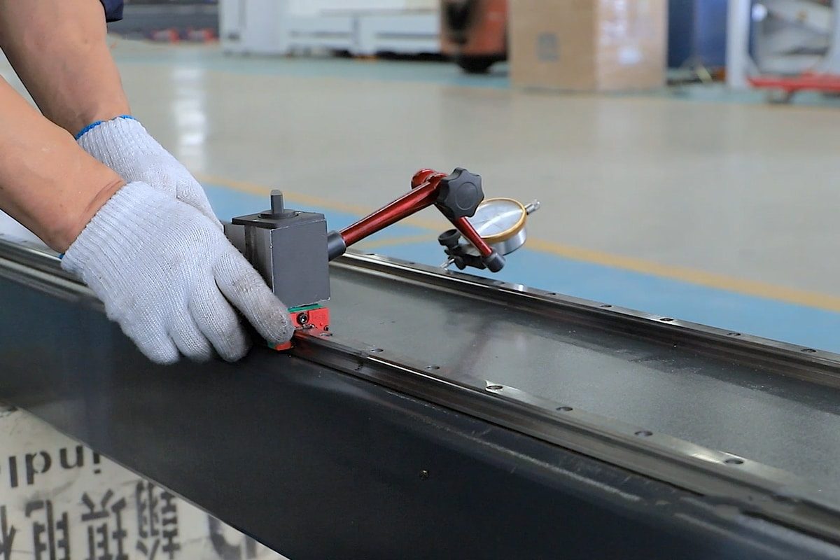
การปรับเทียบและตั้งค่าศูนย์ให้กับเครื่องเราเตอร์ CNC ของคุณ เป็นขั้นตอนสำคัญเพื่อให้มั่นใจได้ว่าผลลัพธ์การตัดเฉือนมีความแม่นยำและสม่ำเสมอ การปรับเทียบจะปรับการเคลื่อนไหวทางกายภาพของเครื่องให้สอดคล้องกับคำสั่งดิจิทัล ในขณะที่การตั้งค่าศูนย์จะกำหนดจุดอ้างอิงที่เส้นทางการตัดทั้งหมดเริ่มต้น หากไม่มีขั้นตอนเหล่านี้ แม้แต่เส้นทางการตัดที่ออกแบบมาอย่างดีก็อาจทำให้การตัดไม่แม่นยำ สิ้นเปลืองวัสดุ หรือทำให้ชิ้นงานเสียหายได้
ในคู่มือนี้ เราจะแนะนำพื้นฐานของการปรับเทียบและการตั้งค่าศูนย์ อธิบายว่าทำไมจึงมีความสำคัญ และให้คำแนะนำทีละขั้นตอนที่ชัดเจนซึ่งเหมาะสำหรับทั้งผู้เริ่มต้นและผู้ใช้งานที่มีประสบการณ์ ตั้งแต่การจัดแนวแกนและความเที่ยงตรงของแกนหมุน ไปจนถึงการตั้งจุดกำเนิดโดยใช้หรือไม่ใช้เครื่องมือวัด บทความนี้จะช่วยให้คุณใช้งานเครื่อง CNC Router ได้อย่างแม่นยำสูงสุด
ทำความเข้าใจพื้นฐาน
ก่อนที่จะลงลึกไปในกระบวนการปรับเทียบและตั้งค่าศูนย์ จำเป็นต้องเข้าใจความหมายของคำศัพท์เหล่านี้ในบริบทของการตัดเฉือนด้วยเครื่อง CNC ก่อน
การปรับเทียบในการตัดเฉือน CNC คืออะไร?
การปรับเทียบในเครื่องตัด CNC คือกระบวนการปรับแต่งเครื่องจักรของคุณอย่างละเอียดเพื่อให้แน่ใจว่าการเคลื่อนไหวจริงของเครื่องจักรตรงกับคำสั่งที่ตั้งโปรแกรมไว้อย่างแม่นยำ เครื่องตัด CNC ทุกเครื่องเคลื่อนที่ไปตามแกน X, Y และ Z โดยใช้มอเตอร์และส่วนประกอบทางกล เช่น สกรูนำ สายพาน หรือรางนำเชิงเส้น เมื่อเวลาผ่านไป ความคลาดเคลื่อนเล็กน้อยอาจเกิดขึ้นได้เนื่องจากความคลาดเคลื่อนทางกล การสึกหรอ หรือการตั้งค่าขั้นตอนที่ไม่ถูกต้อง ตัวอย่างเช่น หากเครื่องจักรของคุณได้รับคำสั่งให้เคลื่อนที่ 100 มม. แต่เคลื่อนที่ได้เพียง 98 มม. ความไม่แม่นยำนั้นจะส่งผลต่อการตัดของคุณ
การปรับเทียบเครื่องเราเตอร์ CNC ของคุณเกี่ยวข้องกับการตรวจสอบการเคลื่อนที่เหล่านี้และปรับการตั้งค่าจำนวนก้าวต่อหน่วยของเครื่องจักรในซอฟต์แวร์ควบคุม กระบวนการนี้อาจรวมถึงการปรับโครงเครื่องให้ได้ฉาก การปรับแกนหมุนเพื่อให้แน่ใจว่าตั้งฉากกับฐาน และการยืนยันว่าระยะการเคลื่อนที่ของแกนทั้งหมดมีความแม่นยำ การปรับเทียบที่ถูกต้องจะคำนึงถึงความคลาดเคลื่อนเล็กน้อยเนื่องจากความคลาดเคลื่อนทางกล ความตึงของสายพาน หรือการสึกหรอ
“การตั้งค่าเป็นศูนย์” หมายความว่าอย่างไร?
การตั้งศูนย์เครื่องเราเตอร์ CNC หมายถึงการกำหนดจุดเฉพาะบนชิ้นงานหรือแท่นเครื่องเป็นจุดเริ่มต้นสำหรับการทำงานของเครื่องจักรทั้งหมด จุด "ศูนย์" นี้จะถูกใช้โดยเครื่องจักรเพื่อทำความเข้าใจว่าควรเริ่มตัด เจาะ หรือแกะสลักที่จุดใดเมื่อเทียบกับวัสดุ โดยทั่วไปแล้วจะรวมถึงการตั้งค่าศูนย์บนแกน X, Y และ Z ซึ่งจะบอกเราเตอร์ถึงตำแหน่งที่แน่นอนของพื้นผิวและขอบของวัสดุ สำหรับโครงการส่วนใหญ่ จุดนี้จะถูกตั้งไว้ที่มุมหรือกึ่งกลางของพื้นผิวด้านบนของชิ้นงาน ขึ้นอยู่กับวิธีการออกแบบเส้นทางการตัดในซอฟต์แวร์ CAM ของคุณ
การตั้งศูนย์ช่วยให้มั่นใจได้ว่าเครื่องจักรของคุณจะตัดในตำแหน่งที่ถูกต้องและในระดับความลึกที่ถูกต้อง หากค่าศูนย์ของแกน Z สูงเกินไป เครื่องมืออาจตัดไม่ลึกพอ หากต่ำเกินไป อาจตัดเข้าไปในโต๊ะได้ ในทำนองเดียวกัน การตั้งศูนย์แกน X หรือ Y ที่ไม่ถูกต้องอาจทำให้ชิ้นงานทั้งหมดคลาดเคลื่อน ส่งผลให้สิ้นเปลืองวัสดุหรือได้ชิ้นส่วนที่ไม่ถูกต้อง การตั้งศูนย์สามารถทำได้ด้วยตนเองโดยการขยับเครื่องจักรไปยังตำแหน่งที่ต้องการและตั้งค่าแกนเป็นศูนย์ หรือทำโดยอัตโนมัติโดยใช้แผ่นสัมผัสหรือโพรบเพื่อความแม่นยำที่สูงขึ้น การตั้งศูนย์ที่ถูกต้องเป็นประโยชน์สำหรับการจัดแนวการออกแบบดิจิทัลของคุณกับการตัดเฉือนในโลกแห่งความเป็นจริง
การปรับเทียบและการตั้งค่าศูนย์ร่วมกันเป็นพื้นฐานสำคัญสำหรับการตัดเฉือนที่แม่นยำ การข้ามขั้นตอนเหล่านี้หรือการดำเนินการอย่างไม่ถูกต้องอาจนำไปสู่การตัดที่ผิดพลาด ความลึกที่ไม่ถูกต้อง และวัสดุที่เสียหาย การเข้าใจบทบาทของขั้นตอนเหล่านี้จะช่วยให้คุณได้ผลลัพธ์ที่มีคุณภาพสูงสม่ำเสมอในทุกโครงการ
การเตรียมตัวก่อนการสอบเทียบ
ก่อนเริ่มการปรับเทียบเครื่องเราเตอร์ CNC สิ่งสำคัญคือต้องเตรียมเครื่องจักรและพื้นที่ทำงานให้พร้อม เพื่อให้มั่นใจในความแม่นยำและความปลอดภัยตลอดกระบวนการ
- การเปิดเครื่องและกำหนดตำแหน่งเริ่มต้น: เริ่มต้นด้วยการเปิดเครื่องและปล่อยให้เครื่องทำการกำหนดตำแหน่งเริ่มต้นจนเสร็จสมบูรณ์ ซึ่งจะเคลื่อนเครื่องไปยังจุดอ้างอิงโดยใช้สวิตช์จำกัดในตัว เพื่อให้แน่ใจว่าเครื่องของคุณมีตำแหน่งเริ่มต้นที่สม่ำเสมอสำหรับการสอบเทียบ
- ตรวจสอบความหลวมหรือการสึกหรอของกลไก: ขั้นตอนต่อไป ให้ทำการตรวจสอบด้วยสายตาและทางกลไกของเครื่องเราเตอร์ CNC ตรวจสอบสกรูที่หลวม ชิ้นส่วนที่ไม่ได้จัดวาง สายพานที่สึกหรอ หรือความเสียหายใดๆ ที่มองเห็นได้ซึ่งอาจส่งผลต่อความแม่นยำในการเคลื่อนที่ ขันชิ้นส่วนกลไกทั้งหมดให้แน่นตามต้องการ และตรวจสอบว่าแกนหมุนติดตั้งอย่างแน่นหนา
- รักษาความสะอาดเครื่องจักร: โดยการทำความสะอาดฐานเครื่องอย่างทั่วถึงเพื่อกำจัดฝุ่น เศษวัสดุ คราบกาว หรือเศษวัสดุที่เหลือจากการทำงานครั้งก่อน ใช้เครื่องดูดฝุ่น แปรง หรือลมเป่าเพื่อกำจัดเศษสิ่งสกปรกออกจากฐานเครื่อง ร่องตัว T ตัวหนีบ และบริเวณโดยรอบ เนื่องจากสิ่งเหล่านี้อาจส่งผลต่อการวัดและการเคลื่อนที่
- การตรวจสอบการติดตั้งเครื่องมือ: ตรวจสอบให้แน่ใจว่าได้ติดตั้งเครื่องมือตัดหรือหัววัดที่ถูกต้องลงในแกนหมุนแล้ว และยืนยันว่าขันแน่นดีแล้ว หากคุณใช้เครื่องมือสอบเทียบ ตรวจสอบให้แน่ใจว่ามีเส้นผ่านศูนย์กลางตรงตามที่คาดไว้ และปราศจากข้อบกพร่องหรือการสึกหรอ
- การติดตั้งโปรแกรมประมวลผลหลังการทำงานที่ถูกต้อง: ติดตั้งซอฟต์แวร์ควบคุมที่เหมาะสม ซึ่งเป็นส่วนประกอบซอฟต์แวร์ที่แปลงเส้นทางการเคลื่อนที่ของเครื่องมือให้เป็นรหัส G ที่เครื่องอ่านได้ เครื่อง CNC และตัวควบคุมแต่ละตัวต้องการโปรแกรมประมวลผลหลังการทำงานที่เข้ากันได้เพื่อสร้างคำสั่งที่มีรูปแบบที่ถูกต้อง รหัสการเคลื่อนที่ และคำแนะนำในการเปลี่ยนเครื่องมือ
- ตรวจสอบเฟิร์มแวร์/การตั้งค่าเครื่องจักร: ตรวจสอบว่าจำนวนก้าวต่อหน่วย (มิลลิเมตรหรือนิ้ว) ได้รับการกำหนดค่าอย่างถูกต้องสำหรับแต่ละแกน นอกจากนี้ ให้ตรวจสอบพารามิเตอร์การเคลื่อนที่อื่นๆ เช่น ความเร่ง ความเร็วสูงสุด และทิศทางการกลับสู่ตำแหน่งเริ่มต้น เพื่อให้แน่ใจว่าตรงกับข้อกำหนดทางกลของเครื่องจักรของคุณ
การเตรียมการอย่างเหมาะสมจะช่วยป้องกันข้อผิดพลาด ประหยัดเวลา และวางรากฐานสำหรับการสอบเทียบที่แม่นยำ
ขั้นตอนการปรับเทียบเครื่องเราเตอร์ CNC ทีละขั้นตอน
การปรับเทียบเครื่องเราเตอร์ CNC ของคุณจะช่วยให้มั่นใจได้ว่าแต่ละแกนเคลื่อนที่ได้ในระยะทางที่แม่นยำตามที่ซอฟต์แวร์ควบคุมกำหนดไว้ หากไม่มีการปรับเทียบที่ถูกต้อง แม้แต่เส้นทางการตัดที่ออกแบบมาอย่างดีที่สุดก็อาจให้ผลลัพธ์ที่ไม่แม่นยำได้ ด้านล่างนี้คือคำแนะนำทีละขั้นตอนที่จะช่วยคุณปรับเทียบเครื่องของคุณเพื่อให้ได้ความแม่นยำสูงสุด
การปรับเทียบแกน (X, Y, Z)
การปรับเทียบแกน X, Y และ Z ช่วยให้มั่นใจได้ว่าเครื่อง CNC ของคุณเคลื่อนที่ได้ระยะทางที่ถูกต้องในแต่ละทิศทางตามคำสั่งที่ตั้งโปรแกรมไว้
- กำหนดจุดเริ่มต้น: วางไม้บรรทัดหรือเครื่องวัดดิจิทัลให้ตรงกับแกน เลื่อนแกนหมุนหรือหัวเครื่อง CNC ไปยังตำแหน่งเริ่มต้นที่ทราบแล้ว และตั้งค่าแกนเป็นศูนย์ในซอฟต์แวร์ควบคุมของคุณ
- สั่งการเคลื่อนที่ตามที่กำหนด: ใช้ซอฟต์แวร์ควบคุมเพื่อเคลื่อนแกนไปในระยะทางที่กำหนด โดยทั่วไปคือ 100 มม. หรือ 4 นิ้ว
- วัดระยะการเคลื่อนที่จริง: วัดระยะที่เครื่องจักรเคลื่อนที่จากจุดเริ่มต้นโดยใช้เวอร์เนียร์คาลิเปอร์หรือไม้บรรทัดวัดความแม่นยำ
- คำนวณและอัปเดตจำนวนก้าวต่อหน่วย: หากมีความคลาดเคลื่อน คุณจะต้องปรับค่าจำนวนก้าวต่อหน่วยในซอฟต์แวร์ควบคุมของคุณโดยใช้สูตรอย่างง่าย
- ทำซ้ำขั้นตอนนี้สำหรับแกนทั้งหมด: ทำซ้ำขั้นตอนนี้สำหรับแกน X, Y และ Z จนกว่าแต่ละแกนจะเคลื่อนที่ได้อย่างแม่นยำและคาดการณ์ได้
การปรับเทียบความตั้งฉากของแกนหมุน
ตรวจสอบให้แน่ใจว่าแกนหมุนตั้งฉากกับฐานเครื่องอย่างสมบูรณ์ เพื่อให้ได้การตัดที่เรียบเนียน สะอาด และแม่นยำ
- ติดตั้งเครื่องมือปรับแนว: ติดตั้งเกจวัดแนวหรือตัววัดระยะแบบหน้าปัดเข้ากับแกนหมุน โดยให้ปลายโพรบกวาดเป็นวงกลมบนแท่นเครื่อง
- กวาดพื้นผิวแท่นพิมพ์: ขยับหรือโยกแกนหมุนด้วยมือเป็นวงกลมเหนือพื้นผิวแท่นพิมพ์ บันทึกความแตกต่างของระดับความสูงที่แสดงบนมาตรวัด
- ตรวจสอบทิศทางการเอียง: หากเข็มชี้ขึ้นหรือลง แสดงว่าแกนหมุนไม่ได้ตั้งฉากกับพื้นผิว สามารถระบุทิศทางการเอียงได้จากการเคลื่อนที่ของตัวชี้วัด
- ปรับแท่นยึดแกนหมุนหรือโครง: คลายโบลต์ยึดและค่อยๆ เลื่อนแกนหมุนหรือใช้แผ่นรองปรับระดับโครงตามต้องการ จนกว่าตัวบ่งชี้จะแสดงค่าที่สม่ำเสมอทั่วทั้งช่วงการกวาด
การปรับเทียบค่าชดเชยความยาวของเครื่องมือ
ระบุตำแหน่งปลายเครื่องมือบนแกน Z ให้เครื่อง CNC ทราบอย่างแม่นยำ เพื่อให้ได้ความลึกในการตัดที่ถูกต้อง
- เลือกวิธีการสอบเทียบความยาวเครื่องมือ: คุณสามารถใช้วิธีการแบบแมนนวล (กระดาษหรือเกจวัดระยะ) หรือเครื่องตั้งค่าเครื่องมืออัตโนมัติ/แผ่นสัมผัสได้
- นำเครื่องมือเข้าใกล้พื้นผิวชิ้นงาน: ค่อยๆ เลื่อนเครื่องมือลงไปทางพื้นผิวจนกระทั่งเริ่มหนีบกระดาษเล็กน้อย โดยทั่วไปถือว่าค่า Z เท่ากับ 0
- ตั้งค่าแกน Z เป็นศูนย์: เมื่อเครื่องมือสัมผัสพื้นผิวแล้ว ให้ตั้งค่าแกน Z เป็นศูนย์ในซอฟต์แวร์ควบคุมของคุณ
- บันทึกความยาวของเครื่องมือลงในตัวควบคุม (ถ้ามี): หากคุณใช้เครื่องมือหลายชิ้น ให้วัดและบันทึกค่าชดเชยของแต่ละเครื่องมือโดยใช้ตารางเครื่องมือของซอฟต์แวร์ของคุณ
- ใช้แผ่นสัมผัส (ไม่จำเป็น): หากใช้แผ่นสัมผัส ให้เชื่อมต่ออย่างถูกต้องและปล่อยให้เครื่องวัดความสูงของแกน Z โดยอัตโนมัติ ซอฟต์แวร์จะบันทึกค่าชดเชยความยาวของเครื่องมือตามความหนาของแผ่นสัมผัส
การทำตามขั้นตอนเหล่านี้จะช่วยเพิ่มความแม่นยำและความน่าเชื่อถือของเครื่องเราเตอร์ CNC ของคุณได้อย่างมาก การปรับเทียบที่ถูกต้องจะช่วยลดข้อผิดพลาดด้านขนาด ทำให้ได้งานตัดที่สม่ำเสมอ และช่วยยืดอายุการใช้งานของเครื่องจักรของคุณ
ขั้นตอนทีละขั้น: การปรับตั้งค่าศูนย์ของเครื่องเราเตอร์ CNC
การตั้งค่าศูนย์ให้กับเครื่อง CNC Router คือกระบวนการบอกเครื่องจักรว่าจุดเริ่มต้นของชิ้นงานอยู่ที่ใดอย่างแม่นยำ เส้นทางการตัดทั้งหมดใน G-code จะถูกคำนวณจากตำแหน่งนี้ หากการตั้งค่าศูนย์ทำไม่ถูกต้อง ชิ้นงานทั้งหมดอาจถูกตัดในตำแหน่งที่ไม่ถูกต้องหรือความลึกที่ไม่ถูกต้อง โปรดทำตามคำแนะนำทีละขั้นตอนต่อไปนี้เพื่อตั้งค่าศูนย์ให้กับเครื่อง CNC Router อย่างแม่นยำ:
การตั้งค่าจุดศูนย์ XY
กำหนดจุดกำเนิดแนวนอนของชิ้นงานเพื่อให้เครื่อง CNC รู้ว่าจะเริ่มการตัดเฉือนจากจุดใด
- เลือกจุดอ้างอิง: ตัดสินใจว่าจะใช้มุมด้านหน้าซ้าย จุดกึ่งกลาง หรือตำแหน่งอื่นใดบนวัสดุของคุณเป็นจุดกำเนิด XY ซึ่งควรตรงกับจุดกำเนิดที่ตั้งไว้ในซอฟต์แวร์ CAM ของคุณ
- จัดตำแหน่งเครื่องมือ: ควบคุมเครื่อง CNC Router ด้วยตนเองโดยใช้ตัวควบคุมหรือซอฟต์แวร์ เพื่อเลื่อนดอกสว่านให้ตรงกับจุดศูนย์ XY ที่คุณเลือกไว้
- ปรับตำแหน่งให้แม่นยำ: ค่อยๆ ขยับเครื่องมืออย่างช้าๆ และระมัดระวังทั้งในทิศทางแกน X และ Y เพื่อให้ได้แนวตรงกับจุดอ้างอิงอย่างแม่นยำ ใช้การจัดแนวด้วยสายตาหรือบล็อกกำหนดตำแหน่งเพื่อความแม่นยำยิ่งขึ้น
- ตั้งค่า X และ Y เป็นศูนย์: เมื่อจัดตำแหน่งเรียบร้อยแล้ว ให้คลิกคำสั่ง “Zero X” และ “Zero Y” ในซอฟต์แวร์ควบคุมของคุณ ขั้นตอนนี้จะกำหนดจุดเริ่มต้นแนวนอนของโปรแกรมของคุณ
การตั้งจุดศูนย์ Z
กำหนดจุดอ้างอิงแนวตั้งเพื่อควบคุมความลึกในการตัดได้อย่างแม่นยำ
- เลือกพื้นผิวศูนย์ของคุณ: ตัดสินใจว่าจะตั้งค่าแกน Z เป็นศูนย์ที่ด้านบนของวัสดุหรือที่ฐานเครื่องจักร การตั้งค่านี้ต้องตรงกับการตั้งค่า CAM ของคุณ
- ใช้กระดาษหรือเกจวัดระยะ (วิธีแบบแมนนวล): วางกระดาษไว้ใต้เครื่องมือแล้วค่อยๆ ลดแกน Z ลงจนกระทั่งเครื่องมือจับกระดาษได้พอดี คุณควรจะรู้สึกถึงแรงต้านเล็กน้อยเมื่อเลื่อนกระดาษ
- ตั้งค่าแกน Z เป็นศูนย์: เมื่อปลายเครื่องมือสัมผัสกับพื้นผิวแล้ว ให้ตั้งค่าแกน Z เป็นศูนย์ในซอฟต์แวร์ของคุณ นำกระดาษออกและยกเครื่องมือขึ้นเล็กน้อยเพื่อหลีกเลี่ยงการชนกัน
- ใช้แผ่นสัมผัส (วิธีอัตโนมัติ, ตัวเลือกเสริม): หากมี ให้เชื่อมต่อแผ่นสัมผัส วางไว้บนพื้นผิวที่เป็นศูนย์ และเรียกใช้คำสั่งตรวจสอบค่า Z ระบบจะตั้งค่า Z เป็นศูนย์โดยอัตโนมัติ โดยชดเชยความหนาของแผ่นสัมผัส
การบันทึกและจัดการค่าชดเชยชิ้นงาน
บันทึกและจัดการการตั้งค่าศูนย์ของคุณเพื่อให้ได้ความแม่นยำในการทำงานซ้ำและรองรับการทำงานหลายชิ้นส่วน
- ทำความเข้าใจเกี่ยวกับค่าชดเชยการทำงาน: ตัวควบคุม CNC ส่วนใหญ่รองรับระบบพิกัดการทำงาน (เช่น G54–G59) ซึ่งช่วยให้คุณสามารถบันทึกจุดศูนย์ที่แตกต่างกันสำหรับงานหรืออุปกรณ์จับยึดต่างๆ ได้
- บันทึกพิกัดการทำงานปัจจุบัน: เมื่อคุณกำหนดจุดศูนย์ X, Y และ Z แล้ว ให้บันทึกค่าเหล่านั้นลงในค่าชดเชยการทำงานเฉพาะ (เช่น G54) วิธีนี้จะช่วยให้คุณกลับไปยังจุดเริ่มต้นเดิมได้แม้หลังจากเครื่องปิดหรือเปลี่ยนเครื่องมือแล้ว
- การกำหนดค่าออฟเซ็ตและเอกสาร: บันทึกค่าออฟเซ็ตแต่ละค่าและสิ่งที่เกี่ยวข้อง (เช่น “อุปกรณ์จับยึด 1 – G55, ชิ้นส่วน 2 – G56”) วิธีนี้จะช่วยให้การสลับงานทำได้อย่างรวดเร็วและเชื่อถือได้
- นำกลับมาใช้ใหม่และตรวจสอบ: ก่อนเริ่มงาน ให้จำค่าออฟเซ็ตที่ถูกต้องและขยับเครื่องไปที่ X0 Y0 Z0 เพื่อตรวจสอบตำแหน่ง ปรับแต่งหากจำเป็นเพื่อให้แน่ใจว่าได้ความแม่นยำในการทำซ้ำ
การทำตามขั้นตอนเหล่านี้จะช่วยให้มั่นใจได้ว่าเครื่อง CNC router ของคุณเริ่มต้นงานแต่ละครั้งในตำแหน่งที่ถูกต้องและตัดได้ความลึกที่ถูกต้อง การตั้งค่าศูนย์อาจดูเหมือนเป็นกระบวนการง่ายๆ แต่การทำอย่างถูกต้องนั้นมีประโยชน์ในการหลีกเลี่ยงข้อผิดพลาดที่มีค่าใช้จ่ายสูงและได้ผลลัพธ์ที่เป็นมืออาชีพ
แนวปฏิบัติที่ดีที่สุดสำหรับการสอบเทียบและการตั้งค่าศูนย์ที่เชื่อถือได้
เพื่อให้ได้ผลลัพธ์ที่สม่ำเสมอและแม่นยำจากเครื่องเราเตอร์ CNC ของคุณ การปรับเทียบและการตั้งค่าศูนย์ต้องดำเนินการอย่างระมัดระวังและสม่ำเสมอ ด้านล่างนี้คือแนวทางปฏิบัติที่ดีที่สุดที่สำคัญเพื่อให้มั่นใจว่าเครื่องของคุณรักษาความแม่นยำและความสม่ำเสมอในระดับสูงได้ตลอดเวลา:
ดำเนินการบำรุงรักษาตามปกติ
การบำรุงรักษาอย่างสม่ำเสมอเป็นรากฐานสำคัญของประสิทธิภาพการทำงานที่เชื่อถือได้และการปรับเทียบที่แม่นยำของเครื่องเราเตอร์ CNC
- การขันให้แน่น: เมื่อเวลาผ่านไป การสั่นสะเทือน ฝุ่นละออง และการสึกหรอทางกล อาจทำให้ชิ้นส่วนต่างๆ หลวมหรือหลุดจากแนวตรง ซึ่งส่งผลโดยตรงต่อความแม่นยำในการตัด การขันน็อตและตัวยึดที่สำคัญทั้งหมดให้แน่น โดยเฉพาะบริเวณโครงเครื่อง ตัวยึดแกนหมุน รางนำทางเชิงเส้น และโครงสร้าง
- การหล่อลื่น: ปฏิบัติตามตารางการหล่อลื่นของเครื่องจักรเพื่อให้สกรูนำ สกรูบอล และรางเชิงเส้นทำงานได้อย่างราบรื่น ใช้สารหล่อลื่นที่แนะนำและหลีกเลี่ยงการใช้มากเกินไป เนื่องจากจาระบีส่วนเกินอาจดึงดูดฝุ่นและเศษสิ่งสกปรกได้ นอกจากนี้ ควรทำความสะอาดชิ้นส่วนที่เคลื่อนที่ได้เป็นระยะเพื่อป้องกันการสะสมของสิ่งสกปรกที่อาจขัดขวางการเคลื่อนที่อย่างราบรื่น
- การตรวจสอบความตั้งฉาก: ตรวจสอบความตั้งฉากของแกนหมุนและโครงเครื่องโดยใช้เกจวัดความตั้งฉากหรือตัววัดความตั้งฉาก การเบี่ยงเบนอาจเกิดจากการเคลื่อนตัวของกลไกหรือการชนกัน และควรแก้ไขโดยทันทีเพื่อรักษาความแม่นยำในการตัด
การบันทึกข้อมูลการสอบเทียบและการสอบเทียบซ้ำเป็นประจำ
การจดบันทึกรายละเอียดการตั้งค่าการปรับเทียบเครื่องเราเตอร์ CNC อย่างละเอียดเป็นวิธีที่ง่ายแต่ทรงประสิทธิภาพในการรักษาความแม่นยำในระยะยาว
- จัดทำบันทึกการสอบเทียบ: บันทึกค่าการสอบเทียบและการปรับแต่งอย่างง่ายๆ บันทึกวันที่ การวัด การเปลี่ยนเครื่องมือ และพฤติกรรมของเครื่องจักร สิ่งนี้จะช่วยให้คุณสังเกตแนวโน้ม ระบุปัญหาที่เกิดขึ้นซ้ำๆ และคืนค่าการตั้งค่าที่เหมาะสมที่สุดได้อย่างรวดเร็วหลังจากมีการเปลี่ยนแปลงฮาร์ดแวร์หรือพฤติกรรมที่ไม่คาดคิด
- กำหนดตารางการปรับเทียบค่าอย่างสม่ำเสมอ: สำหรับการใช้งานเบา การตรวจสอบรายเดือนอาจเพียงพอ แต่สำหรับการใช้งานประจำวัน อาจจำเป็นต้องตรวจสอบพารามิเตอร์สำคัญทุกสัปดาห์หรือแม้กระทั่งทุกวัน การกำหนดตารางการปรับเทียบค่าอย่างสม่ำเสมอจะช่วยให้ตรวจพบการเปลี่ยนแปลงเล็กน้อยได้ตั้งแต่เนิ่นๆ ซึ่งจะช่วยรักษาประสิทธิภาพและความน่าเชื่อถือสูงที่เครื่อง CNC router ของคุณได้รับการออกแบบมาให้ใช้งานได้
การใช้ระบบตรวจสอบเพื่อความสม่ำเสมอ
ระบบการวัดระยะเป็นเครื่องมือที่มีประสิทธิภาพซึ่งช่วยเพิ่มความแม่นยำและความสม่ำเสมอของกระบวนการสอบเทียบและตั้งค่าศูนย์ของเครื่องเราเตอร์ CNC โดยทั่วไปจะใช้แผ่นสัมผัสเพื่อตั้งค่าจุดศูนย์ Z โดยอัตโนมัติ เมื่อเครื่องมือสัมผัสกับแผ่นนำไฟฟ้า เครื่องจะบันทึกความสูงที่แน่นอนและปรับค่าตามความหนาของแผ่น ทำให้ได้จุดกำเนิดแกน Z ที่แม่นยำสม่ำเสมอ สำหรับการเปลี่ยนเครื่องมือ สามารถติดตั้งเซ็นเซอร์วัดความยาวเครื่องมืออัตโนมัติเพื่อวัดและบันทึกความยาวที่แน่นอนของเครื่องมือแต่ละชิ้น ช่วยลดการตั้งค่าศูนย์ด้วยตนเองระหว่างการทำงาน การบูรณาการระบบการวัดระยะเข้ากับขั้นตอนการทำงานของคุณจะช่วยให้กระบวนการสอบเทียบและการตั้งค่าศูนย์เป็นมาตรฐานเดียวกัน
การพิจารณาด้านสิ่งแวดล้อม
การเปลี่ยนแปลงของอุณหภูมิ ความชื้น ฝุ่นละออง และการสั่นสะเทือน ล้วนเป็นปัจจัยที่ส่งผลต่อความแม่นยำได้
- การเปลี่ยนแปลงอุณหภูมิอาจทำให้วัสดุขยายตัวหรือหดตัว เพื่อผลลัพธ์ที่ดีที่สุด ควรใช้งานเครื่อง CNC router ในสภาพแวดล้อมที่มีการควบคุมอุณหภูมิ และหลีกเลี่ยงการปรับเทียบเครื่องทันทีหลังจากเปิดเครื่อง เนื่องจากชิ้นส่วนภายในอาจยังไม่ร้อนขึ้น
- ความชื้นอาจทำให้เกิดการกัดกร่อนบนชิ้นส่วนโลหะและจุดเชื่อมต่อทางไฟฟ้าหากไม่ได้รับการควบคุมอย่างเหมาะสม ควรใช้เครื่องลดความชื้นหรือระบบควบคุมสภาพอากาศหากโรงงานของคุณอยู่ในพื้นที่ที่มีความชื้นสูง
- ฝุ่นละอองและเศษวัสดุจากการทำงานของเครื่องจักรอาจสะสมอยู่ในรางเลื่อน สกรูบอล และเซ็นเซอร์ ทำให้เกิดการติดขัดหรือการเคลื่อนที่ไม่แม่นยำ ควรทำความสะอาดเป็นประจำด้วยเครื่องดูดฝุ่นหรือลมเป่า
- การสั่นสะเทือน ไม่ว่าจะมาจากตัวเครื่องเองหรืออุปกรณ์ใกล้เคียง อาจทำให้สลักเกลียวหลวมหรือทำให้การจัดแนวทางกลเปลี่ยนแปลงไปทีละน้อย ควรวางเครื่อง CNC router บนพื้นผิวที่มั่นคงและได้ระดับ และตรวจสอบความหลวมทางกลเป็นระยะๆ
การปฏิบัติตามแนวทางปฏิบัติที่ดีที่สุดเหล่านี้ จะช่วยสร้างรากฐานที่มั่นคงสำหรับความแม่นยำและประสิทธิภาพในระยะยาวของเครื่องเราเตอร์ CNC ของคุณ
เมื่อใดควรปรับเทียบหรือตั้งค่าศูนย์ใหม่
การปรับเทียบหรือการตั้งค่าศูนย์ใหม่ให้กับเครื่องเราเตอร์ CNC ของคุณไม่ควรทำเพียงครั้งเดียว – ทั้งสองอย่างจำเป็นต้องทำซ้ำภายใต้เงื่อนไขเฉพาะเพื่อให้แน่ใจว่าเครื่องของคุณยังคงทำงานได้อย่างดีที่สุด สถานการณ์สำคัญที่จำเป็นต้องปรับเทียบหรือตั้งค่าศูนย์ใหม่มีดังต่อไปนี้
- หลังจากประกอบเครื่องหรือเคลื่อนย้ายเครื่อง: หากคุณเพิ่งประกอบเครื่องเราเตอร์ CNC หรือเคลื่อนย้ายไปยังตำแหน่งใหม่ การปรับเทียบใหม่เป็นสิ่งจำเป็น การเคลื่อนย้ายเครื่องอาจส่งผลต่อการจัดแนวเฟรม ความเที่ยงตรงของแกนหมุน และระยะการเคลื่อนที่ของแกน เนื่องจากมีการเลื่อนหรือการสั่นสะเทือนระหว่างการขนส่ง
- หลังการเปลี่ยนหรือบำรุงรักษาชิ้นส่วน: ทุกครั้งที่คุณเปลี่ยนสายพาน มอเตอร์ สกรูนำ แกนหมุน หรือชิ้นส่วนสำคัญอื่นๆ ให้ทำการปรับเทียบแกนใหม่และตรวจสอบความเที่ยงตรงอีกครั้ง ชิ้นส่วนใหม่ๆ อาจมีพฤติกรรมที่แตกต่างออกไปหรืออาจเปลี่ยนแปลงการตั้งค่าการจัดแนวเดิมได้
- หลังจากเครื่อง CNC ชนหรือเกิดข้อผิดพลาดในการกำหนดเส้นทางการตัด: หากเครื่อง CNC ชนกับวัสดุหรือโต๊ะเนื่องจากข้อผิดพลาดในการเขียนโปรแกรมหรือการจัดแนวที่ไม่ถูกต้อง อาจทำให้ตำแหน่งศูนย์ผิดเพี้ยนหรือทำให้ชิ้นส่วนกลไกเสียหายได้ ควรตรวจสอบเครื่องและตั้งค่าศูนย์ใหม่ (หรือปรับเทียบใหม่) ก่อนเริ่มงานครั้งต่อไปเสมอ
- เมื่อเปลี่ยนวัสดุหรือเครื่องมือ: วัสดุที่แตกต่างกันอาจต้องการการตั้งค่า Z-zero ใหม่ ขึ้นอยู่กับความสูงหรือความหนาของพื้นผิว ในทำนองเดียวกัน ทุกครั้งที่คุณเปลี่ยนเครื่องมือ คุณต้องตั้งค่า Z-zero ใหม่ หรือใช้โพรบวัดระยะชดเชยความยาวของเครื่องมือ
- หลังจากอัปเดตเฟิร์มแวร์หรือซอฟต์แวร์: การเปลี่ยนแปลงซอฟต์แวร์หรือเฟิร์มแวร์อาจรีเซ็ตหรือเปลี่ยนแปลงค่าการปรับเทียบ การตั้งค่าเริ่มต้น หรือพฤติกรรมของตัวประมวลผลหลังการทำงาน หลังจากอัปเดตแล้ว โปรดตรวจสอบให้แน่ใจว่าค่าขั้นตอนต่อหน่วย ค่าชดเชย และความยาวเครื่องมือของเครื่องยังคงถูกต้อง
- ควรทำเป็นประจำตามกำหนด: แม้ว่าจะไม่มีตัวกระตุ้นที่เฉพาะเจาะจง การปรับเทียบใหม่เป็นประจำก็เป็นสิ่งที่ดี สำหรับการใช้งานเป็นงานอดิเรกเบาๆ การตรวจสอบรายเดือนอาจเพียงพอ สำหรับการผลิตเชิงพาณิชย์ทุกวัน การตรวจสอบรายสัปดาห์หรือแม้แต่รายวันจะช่วยให้มั่นใจได้ถึงผลลัพธ์ที่สม่ำเสมอ
- เมื่อความแม่นยำของขนาดลดลง: หากคุณสังเกตเห็นว่าชิ้นส่วนต่างๆ ไม่สามารถประกอบเข้าด้วยกันได้อย่างถูกต้อง การตัดไม่ได้ขนาด หรือความลึกของการแกะสลักไม่สม่ำเสมอ นั่นเป็นสัญญาณที่ชัดเจนว่าจำเป็นต้องปรับเทียบใหม่หรือตั้งค่าศูนย์ใหม่ การทดสอบตัดบนวัสดุเหลือใช้สามารถช่วยยืนยันเรื่องนี้ได้
การปรับเทียบและตั้งค่าศูนย์ใหม่เป็นประจำจะช่วยให้เครื่องเราเตอร์ CNC ของคุณทำงานได้อย่างแม่นยำตามที่คุณคาดหวัง ควรทำให้การปรับเทียบและการตั้งค่าศูนย์ใหม่เป็นส่วนหนึ่งของขั้นตอนการทำงานประจำของคุณ เพื่อให้ได้ผลลัพธ์ที่มีคุณภาพสูงและน่าเชื่อถือทุกครั้ง
สรุป
การปรับเทียบและตั้งค่าศูนย์ของเครื่องเราเตอร์ CNC เป็นขั้นตอนพื้นฐานที่ช่วยให้มั่นใจได้ว่าเครื่องจักรของคุณทำงานได้อย่างแม่นยำ สม่ำเสมอ และเชื่อถือได้ การปรับเทียบแกน X, Y และ Z อย่างระมัดระวัง การจัดแนวแกนหมุน และการตั้งค่าจุดศูนย์อย่างแม่นยำ จะเป็นการวางรากฐานสำหรับการตัดเฉือนที่มีคุณภาพสูงและขั้นตอนการทำงานที่มีประสิทธิภาพ การทำให้การปรับเทียบและการตั้งค่าศูนย์เป็นส่วนหนึ่งของกระบวนการทำงานของคุณเป็นประจำ จะช่วยให้คุณหลีกเลี่ยงข้อผิดพลาดที่มีค่าใช้จ่ายสูง ยืดอายุการใช้งานของอุปกรณ์ และบรรลุผลลัพธ์ระดับมืออาชีพได้อย่างมั่นใจ
หากคุณกำลังมองหาเครื่องเราเตอร์ CNC ที่เชื่อถือได้และมีประสิทธิภาพสูงAccTek CNCคือตัวเลือกที่คุณวางใจได้ ไม่ว่าคุณจะอยู่ในธุรกิจงานไม้ งานป้าย งานแปรรูปโลหะ หรือการผลิตแบบกำหนดเอง AccTek มีโซลูชัน CNC ที่หลากหลายซึ่งปรับให้เหมาะกับวัสดุและการใช้งานที่แตกต่างกัน พร้อมด้วยการสนับสนุนทางเทคนิคอย่างมืออาชีพและบริการลูกค้าที่ตอบสนองรวดเร็ว AccTek รับประกันว่าผู้ใช้ทุกคนสามารถใช้งานได้อย่างมั่นใจและได้ผลลัพธ์ที่ยอดเยี่ยม